User Manual Appendix B
GFK-1742F Jan 2020
DSM314 Communications Request Instructions 407
B-4.2 DSM Parameter Load COMM REQ Example
This example is used as the basis for the following section, “Section 5: COMM REQ Ladder
Logic Example.” In this example, the following specifications are given:
•
The DSM module is mounted in Rack 0, Slot 7 of the PLC.
•
The Command Block’s starting address is %R0196.
•
The Status Word is located at %R0195.
•
16 parameters are to be sent.
•
The COMM REQ’s FT (fault) output drives a Set Coil.
•
DSM Parameter 1 is considered critical in this example application. The last two
rungs of the “COMM REQ Ladder Logic Example” (see Section 5) verify that
Parameter 1 received the correct value via the COMM REQ.
•
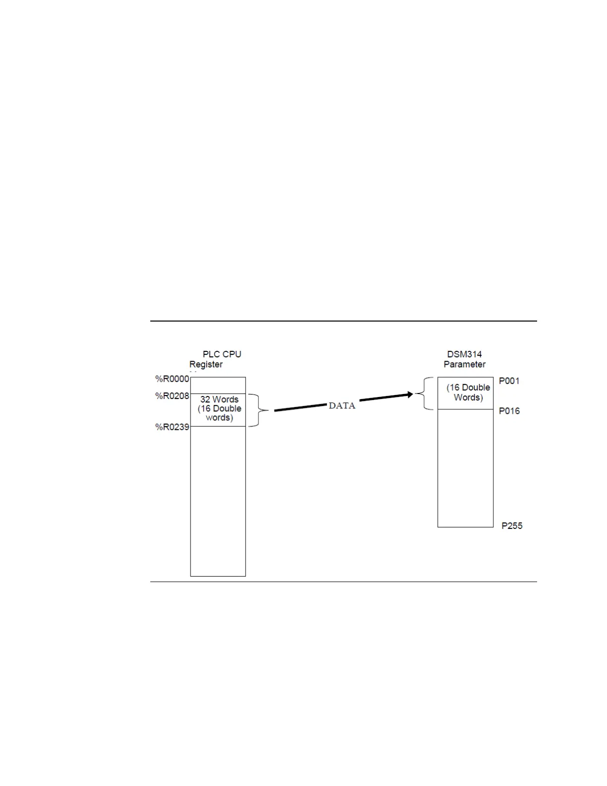
The data in 32 words (16 double words) of memory, %R0208 through %R0239, are
copied to 16 double word parameter registers, P001 through P016, in DSM314
parameter memory. This transfer of data is illustrated in the next figure:
Figure 185: Data Transfer for Parameter Load COMM REQ Example
 Loading...


