User Manual Chapter 3
GFK-1742F Jan 2020
Installing and Wiring the DSM314 50
All four connectors provide similar analog and digital I/O circuits. Only Axis 1 and Axis 2 can
be configured to control digital servos. If digital servos are used, both Axis 1 and Axis 2 must
be configured for Digital Servo mode. When Axis 1 and Axis 2 are configured for digital
servos, Axis 3 can be used for Analog Velocity Interface Servo or Aux Axis control. Axis 4 is
not available for Analog Velocity Interface Servo, Torque Interface Servo or Aux Axis control
when Axis 1 and 2 are configured for digital servos.
When Axis 1 is configured for Analog Servo control (Torque Interface or Velocity Interface),
Axis 2 - Axis 4 are also available for Analog Servo (Torque Interface or Velocity Interface) or
Aux Axis control. Aux Axis functions include position input for Follower Master axes and
internal (virtual master) command generation.
Any of these four connectors used in a system typically is cabled to an appropriate Terminal
Board with cable IC693CBL324 (1 meter) or IC693CBL325 (3 meters). Three different
terminal boards provide screw terminals for connecting to external devices. The terminal
boards are described later in the “Terminal Board” section of this chapter.
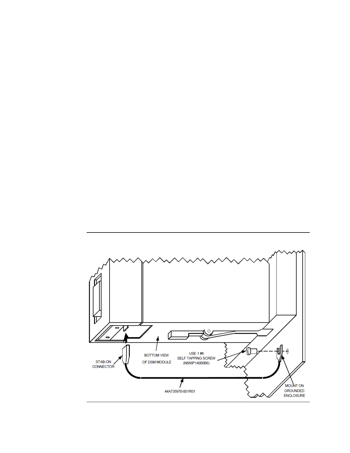
3.1.4 Shield Ground Connection
The DSM314 faceplate shield must be connected to frame ground. This connection from
the DSM314 to frame ground can be made using the green ground wire (part number
44A735970-001R01) provided with the module. This wire has a stab-on connector on one
end for connection to a ¼ inch terminal on the bottom of the DSM314 module and a
terminal on the other end for connection to a grounded enclosure.
Figure 32: Connecting the Shield Ground
 Loading...


