User Manual Chapter 14
GFK-1742F Jan 2020
Local Logic Configuration 321
14.3 CTL01-CTL24 Bit Configuration Selections
Each of the bits CTL01-CTL24 are individually configurable. CTL17-CTL24 default to the %Q
digital output control bits for axis 1 - axis 4. The configuration choices are shown in the
following table.
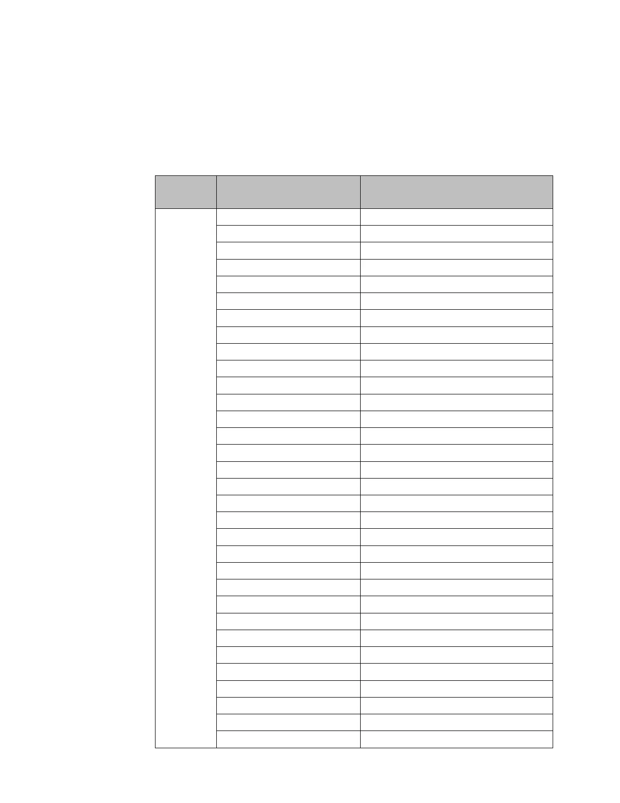
Table 72: CTL Bit Configuration Selections
Allowed Configuration Values
for Bit Source
Faceplate 24v Input Axis 3
Faceplate 24v Input Axis 3
Faceplate 24v Input Axis 4
Faceplate 24 v Input Axis 4
Faceplate 24 v Input Axis 4
Input Strobe1 Level Axis 1
Input Strobe 2 Level Axis 1
Input Strobe 1 Level Axis 2
Input Strobe 2 Level Axis2
Input Strobe 1 Level Axis 3
Input Strobe 2 Level Axis 3
Faceplate 5v Input Axis 4
Faceplate 5v Input Axis 4
CTL bit under Local Logic control
Local Logic Program Active
Serial Non-Acknowledge Protocol (FBSA) Bit 1
Serial Non-Acknowledge Protocol (FBSA) Bit 2
Serial Non-Acknowledge Protocol (FBSA) Bit 3
Serial Non-Acknowledge Protocol (FBSA) Bit 4
Faceplate 24v Output Control Axis 1 (OUT1_A)
Faceplate 5v Output Control Axis 1 (OUT3_A)
 Loading...


