multi EA 5000 Table of figures
185
Table of figures
Figure 1 Operating modes of the multi EA 5000 ............................................................................................................ 17
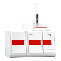
Figure 2 Front view in vertical operation mode ................................................................................................................ 19
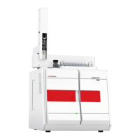
Figure 3 Basic module in horizontal operation mode....................................................................................................... 19
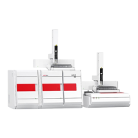
Figure 4 Basic module with a sampling module and a detection module....................................................................... 20
Figure 5 Interfaces on the rear of the device .................................................................................................................... 21
Figure 6 Power connection, power switch......................................................................................................................... 21
Figure 7 Interfaces for detector modules and sampling modules.................................................................................... 22
Figure 8 Connection for the sensors and the combustion furnace in the device ............................................................ 22
Figure 9 Connections for the auto-protection valve assembly and transfer line ............................................................ 23
Figure 10 Hose diagram for horizontal operation .............................................................................................................. 24
Figure 11 Hose diagram for vertical operation ................................................................................................................... 25
Figure 12 Gas connections at the rear of the device........................................................................................................... 26
Figure 13 Gas connections on the gas box.......................................................................................................................... 27
Figure 14 Connections on the combustion tube ................................................................................................................. 27
Figure 15 Combustion furnace in the vertical and horizontal operating mode ................................................................ 28
Figure 16 Multi-purpose combustion tube.......................................................................................................................... 28
Figure 17 Membrane dryer................................................................................................................................................... 29
Figure 18 Space required for the basic device and modules (vertical operation) ............................................................. 33
Figure 19 Space required for the basic device and modules (horizontal operation) ........................................................ 34
Figure 20 Media connections of the rear of the device ...................................................................................................... 36
Figure 21 Basic module with detection module and sampling module............................................................................. 44
Figure 22 Rear of the nitrogen detector.............................................................................................................................. 45
Figure 23 Absorber ............................................................................................................................................................... 46
Figure 24 Connecting detection modules to the basic module .......................................................................................... 47
Figure 25 Design of the chlorine detector (without measuring cell)................................................................................. 50
Figure 26 Measuring cell "sensitive" with lid........................................................................................................................ 51
Figure 27 Equipped measuring cell...................................................................................................................................... 51
Figure 28 Combined electrode ............................................................................................................................................. 52
Figure 29 Measuring cell "high concentration" with lid....................................................................................................... 52
Figure 30 Measuring cell "high sensitive" with lid ............................................................................................................... 53
Figure 31 Equipped measuring cell...................................................................................................................................... 54
Figure 32 Sensor electrode................................................................................................................................................... 55
Figure 33 Exhaust connection.............................................................................................................................................. 55
Figure 34 Platinum electrode with salt bridge.................................................................................................................... 56
Figure 35 Silver electrode..................................................................................................................................................... 56
Figure 36 Rear of the chlorine detector............................................................................................................................... 57
Figure 37 Measuring cell connections ................................................................................................................................. 58
Figure 38 Connection of the heated gas transfer lines to the sulfuric acid container ...................................................... 58
Figure 39 Gas infeed tube with PTFE connector................................................................................................................. 59
Figure 40 Gas infeed to the "sensitive" measuring cell ....................................................................................................... 59

 Loading...


