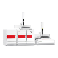
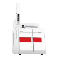
multi EA 5000 Carbon analysis with the TOC module
97
EC/OC determination requires the use of the EC/OC combustion tube.
For the connection to the basic module, hose 82 is removed from the "sample in" mea-
suring gas inlet on the rear of the detection module. The "sample in" measuring gas inlet
is connected to the "Sample OUT N/S/C" outlet on the basic module.
12.2 Installation
NOTICE
Connecting or disconnecting electrical contacts may damage the sensitive electronic
components of the basic module and of the detection module.
¡ Always connect the modules to power when they are switched off.
} Place the detection module to the immediate left of the basic module.
} Connect the supplied power cable to the power cable connection on the rear of the
module and to an earthed socket. Observe the permissible maximum voltage!
} Connect the detection module to the basic module via the two interfaces:
– 9-pin interface cable
"C-NDIR" interface on the rear of the detection module
"C-NDIR" interface on the rear of the basic module
– 25-pin interface cable
"external (in) interface on the rear of the detection module
"External" interface on the rear of the basic module
} Install the halogen trap and the water traps in the detection module as shown in the
illustration. Connect both with hose 81.
} Install the TIC reactor. Connect the TIC reactor to the water traps. Connect the TIC re-
actor to the condensate pump via hose 86.
} Connect the measuring gas hose (hose 80) from the basic module to the lateral out-
let of the TIC reactor.
Hose 80 is connected to the condensation coil outlet in the basic module later.
} Place the waste canister to the left of the detection module.
} Connect the waste hose to the "waste" outlet on the rear of the detection module.
Route the waste hose into the waste canister.
} Leave the "sample out" outlet unconnected or connect it to the measuring gas inlet of
the next detection module.
 Loading...


