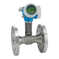
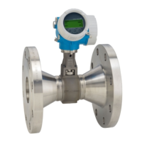
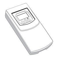
Proline Prowirl F 200 PROFIBUS PA Installation
Endress+Hauser 23
6.1.2 Requirements from environment and process
Ambient temperature range
Compact version
Measuring device Non-Ex: –40 to +80 °C (–40 to +176 °F)
1)
Ex i: –40 to +70 °C (–40 to +158 °F)
1)
EEx d/XP version: –40 to +60 °C (–40 to +140 °F)
1)
ATEX II1/2G Ex d, Ex ia: –40 to +60 °C (–40 to +140 °F)
1)
Local display –20 to +70 °C (–4 to +158 °F)
1)
1) Additionally available as order code for "Test, certificate", option JN "Transmitter ambient temperature –50
°C (–58 °F)".
Remote version
Transmitter Non-Ex: –40 to +80 °C (–40 to +176 °F)
1)
Ex i: –40 to +80 °C (–40 to +176 °F)
1)
Ex d: –40 to +60 °C (–40 to +140 °F)
1)
ATEX II1/2G Ex d, Ex ia: –40 to +60 °C (–40 to +140 °F)
1)
Sensor Non-Ex: –40 to +85 °C (–40 to +185 °F)
1)
Ex i: –40 to +85 °C (–40 to +185 °F)
1)
Ex d: –40 to +85 °C (–40 to +185 °F)
1)
ATEX II1/2G Ex d, Ex ia: –40 to +85 °C (–40 to +185 °F)
1)
Local display –20 to +70 °C (–4 to +158 °F)
1)
1) Additionally available as order code for "Test, certificate", option JN "Transmitter ambient temperature –50
°C (–58 °F)".
‣
If operating outdoors:
Avoid direct sunlight, particularly in warm climatic regions.
Thermal insulation
For optimum temperature measurement and mass calculation, heat transfer at the sensor
must be avoided for some fluids. This can be ensured by installing thermal insulation. A
wide range of materials can be used for the required insulation.
This applies for:
• Compact version
• Remote sensor version
The maximum insulation height permitted is illustrated in the diagram:
A0019212
1 Maximum insulation height
 Loading...


