System integration Proline Prowirl F 200 PROFIBUS PA
66 Endress+Hauser
Configuration MODETOT ←
Analog Output block 1 → 69 Input values AO ←
Discrete Input block 1 to 2 → 70 Output values DI →
Discrete Output block 1 to
3
→ 70 Input values DO ←
Defined order of modules
The measuring device works as a modular PROFIBUS slave. In contrast to a compact slave,
a modular slave has a variable design and consists of several individual modules. The
device master file (GSD) contains a description of the individual modules (input and output
data) along with their individual properties.
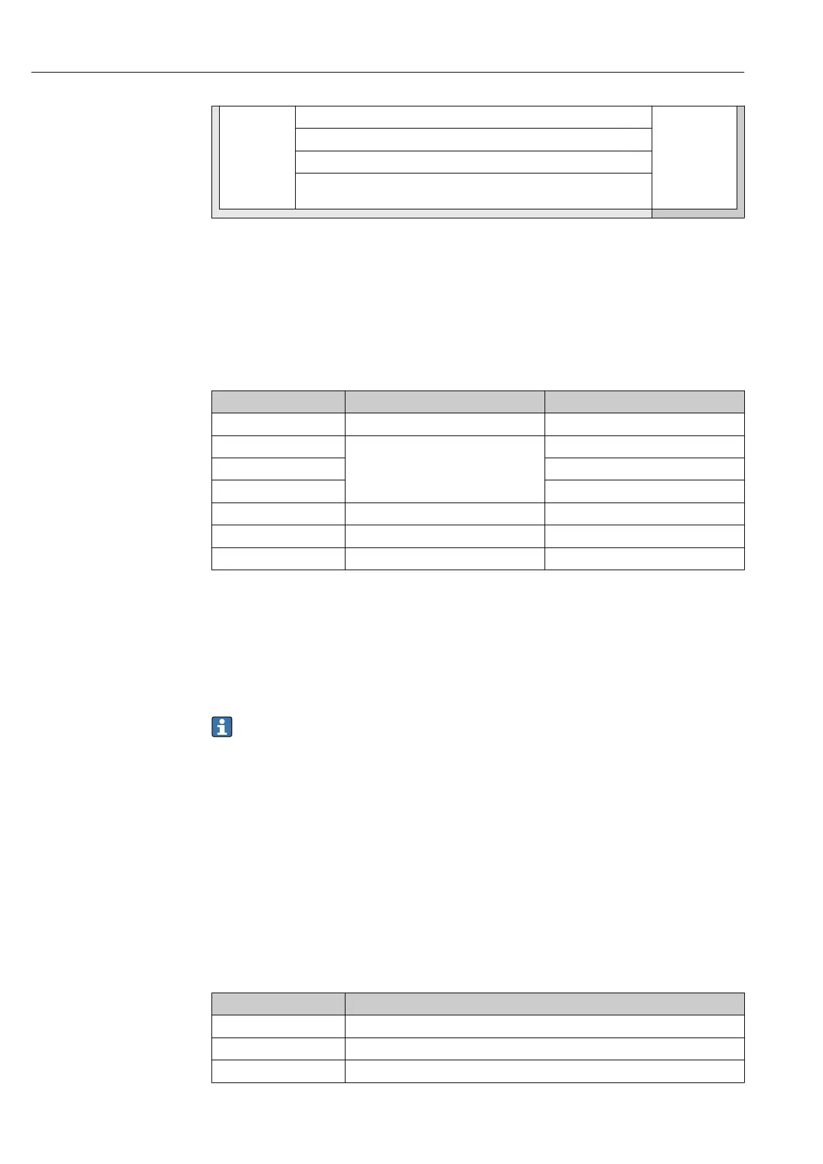
The modules are permanently assigned to the slots, i.e. when configuring the modules, the
order and the arrangement of the modules must be respected.
Slot Module Function block
1…4 AI Analog Input block 1 to 4
5
TOTAL or
SETTOT_TOTAL or
SETOT_MODETOT_TOTAL
Totalizer block 1
6 Totalizer block 2
7 Totalizer block 3
8 AO Analog Output block 1
9…10 DI Discrete Input block 1 to 2
11…13 DO Discrete Output block 1 to 3
To optimize the data throughput rate of the PROFIBUS network, it is advisable to only
configure modules that are processed in the PROFIBUS master system. If this results in
gaps between the configured modules, these gaps must be assigned to the
EMPTY_MODULE.
9.3.2 Description of the modules
The data structure is described from the perspective of the PROFIBUS master:
• Input data: Are sent from the measuring device to the PROFIBUS master.
• Output data: Are sent from the PROFIBUS master to the measuring device.
AI module (Analog Input)
Transmit an input variable from the measuring device to the PROFIBUS master (Class 1).
The selected input variable, along with the status, is cyclically transmitted to the
PROFIBUS Master (Class 1) via the AI module. The input variable is depicted in the first
four bytes in the form of a floating point number as per the IEEE 754 standard. The fifth
byte contains standardized status information pertaining to the input variable.
Four Analog Input blocks are available (slot 1 to 4).
Selection: input variable
The input variable can be specified using the CHANNEL parameter.
CHANNEL Input variable
33122 Volume flow
32961 Mass flow
33093 Corrected volume flow