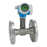
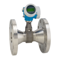
Proline Prowirl F 200 PROFIBUS PA Electrical connection
Endress+Hauser 35
Supply voltage for a compact version without a local display
1)
Order code for "Output" Minimum
terminal voltage
2)
Maximum
terminal voltage
Option G: PROFIBUS PA, pulse/frequency/
switch output
≥ DC 9 V DC 32 V
1) In event of external supply voltage of the PROFIBUS DP/PA coupler
2) The minimum terminal voltage increases if local operation is used: see the following table
Increase in minimum terminal voltage
Local operation
Increase in minimum
terminal voltage
Order code for "Display; Operation", option C:
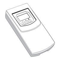
Local operation SD02
+ DC 1 V
Order code for "Display; Operation", option E:
Local operation SD03 with lighting
(backlighting not used)
+ DC 1 V
Order code for "Display; Operation", option E:
Local operation SD03 with lighting
(backlighting used)
+ DC 3 V
7.1.7 Preparing the measuring device
1. Remove dummy plug if present.
2. NOTICE
Insufficient sealing of the housing!
Operational reliability of the measuring device could be compromised.
‣
Use suitable cable glands corresponding to the degree of protection.
If measuring device is delivered without cable glands:
Provide suitable cable gland for corresponding connecting cable .
3. If measuring device is delivered with cable glands:
Observe cable specification .
7.2 Connecting the measuring device
NOTICE
Limitation of electrical safety due to incorrect connection!
‣
Have electrical connection work carried out by correspondingly trained specialists only.
‣
Observe applicable federal/national installation codes and regulations.
‣
Comply with local workplace safety regulations.
‣
For use in potentially explosive atmospheres, observe the information in the device-
specific Ex documentation.
7.2.1 Connecting the remote version
L
WARNING
Risk of damaging the electronic components!
‣
Ground the remote version and in doing so connect the sensor and transmitter to the
same potential equalization.
‣
Only connect the sensor to a transmitter with the same serial number.
The following procedure (in the action sequence given) is recommended for the remote
version:
 Loading...


