Electrical connection Proline Prowirl F 200 PROFIBUS PA
42 Endress+Hauser
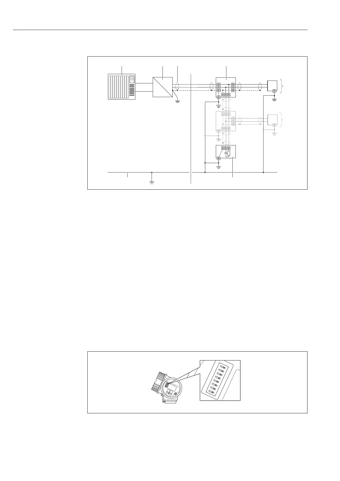
PROFIBUS-PA
A0019004
12 Connection example for PROFIBUS-PA
1 Control system (e.g. PLC)
2 Segment coupler PROFIBUS DP/PA
3 Cable shield
4 T-box
5 Measuring device
6 Local grounding
7 Bus terminator
8 Potential matching line
7.4 Hardware settings
7.4.1 Setting the device address
PROFIBUS PA
The address must always be configured for a PROFIBUS DP/PA device. The valid address
range is between 1 and 126. In a PROFIBUS DP/PA network, each address can only be
assigned once. If an address is not configured correctly, the device is not recognized by the
master. All measuring devices are delivered from the factory with the device address 126
and with the software addressing method.
A0015686
13 Address switch in the connection compartment