Electrical connection Proline Prowirl F 200 PROFIBUS PA
32 Endress+Hauser
7.1.3 Terminal assignment
Transmitter
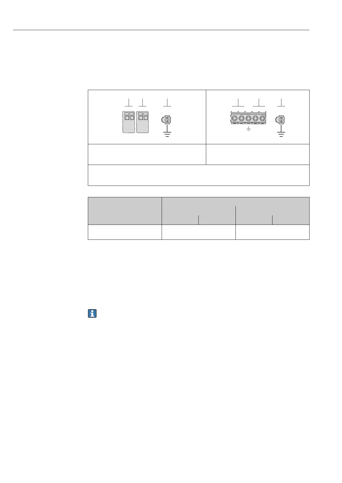
Connection version for PROFIBUS PA, pulse/frequency/switch output
A0013570
A0018161
Maximum number of terminals Maximum number of terminals for order code for
"Accessory mounted", option NA "Overvoltage
protection"
1
2
3
Output 1: PROFIBUS PA
Output 2 (passive: pulse/frequency/switch output
Ground terminal for cable shield
Order code for "Output" Terminal numbers
Output 1 Output 2
1 (+) 2 (-) 3 (+) 4 (-)
Option G
1) 2)
PROFIBUS PA
Pulse/frequency/switch output
(passive)
1) Output 1 must always be used; output 2 is optional.
2) PROFIBUS PA with integrated reverse polarity protection.
Remote version
In the case of the remote version, the sensor and transmitter are mounted separately from
one another and connected by a connecting cable. The sensor is connected via the
connection housing while the transmitter is connected via the connection compartment of
the wall holder unit.
The way the transmitter wall holder is connected depends on the measuring device
approval and the version of the connecting cable used.
Connection is only possible via terminals:
• For approvals Ex n, Ex tb and cCSAus Div. 1
• If a reinforced connecting cable is used
The connection is via an M12 connector:
• For all other approvals
• If the standard connecting cable is used
Connection to the connection housing of the sensor is always via the terminals
(tightening torque for terminals: 1.2 to 1.7 Nm).