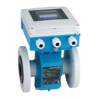
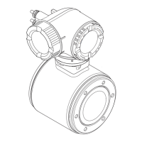
Electrical connection Proline Promag L 400 PROFIBUS DP
36 Endress+Hauser
PROFIBUS DP signal transmission
Order code for "Output" and "Input" Terminal numbers
26 (RxD/TxD-P) 27 (RxD/TxD-N)
Option L B A
Order code for "Output":
Option L: PROFIBUS DP, for use in non-hazardous areas and Zone 2/div. 2
Remote version
E1
E2
GND
E
S1
E1
E2
S2
GND
E
S
5
7
4
37
42 41
6
5
7
8
4
37 36
n.c. n.c.
21
1
2
n.c.
42 41
A
B
A0020534
9 Remote version terminal assignment
A Transmitter wall-mount housing
B Sensor connection housing
1 Electrode cable
2 Coil current cable
n.c. Not connected, insulated cable shields
Terminal No. and cable colors: 6/5 = brown; 7/8 = white; 4 = green; 36/37 = yellow
7.1.4 Preparing the measuring device
1. Remove dummy plug if present.
2. If measuring device is delivered with cable glands:
Observe cable specification (→ 33).
7.1.5 Preparing the connecting cable for the remote version
When terminating the connecting cable, pay attention to the following points:
• In the case of electrode cables, make sure that the ferrules do not touch the core shields
on the sensor side. Minimum distance = 1 mm (exception: green “GND” cable)
• In the case of coil current cables, insulate one core of the three-core wire at the level of
the core reinforcement. You only require two cores for the connection.
• Fit the fine-wire cores with ferrules.

 Loading...


