DSG-423 GENERAL INFORMATION
01-10
PCV System Malfunction
A malfunctioning Positive Crankcase Ventilation
System (closed type) may be indicated by loping or
rough engine idle. Do not attempt to compensate for this
idle condition by disconnecting the PCV system and
making an air bypass or idle speed adjustment.
CAUTION: The removal of the PCV system from the
engine will adversely affect fuel economy and
engine crankcase ventilation with resultant
shortening of engine life.
Engine Oil Leaks
NOTE: When diagnosing engine oil leaks, the source
and location of the leak must be positively identified
prior to service.
Prior to performing this procedure, clean the cylinder
block, cylinder heads, valve covers, oil pan and flywheel
with a suitable solvent to remove all traces of oil.
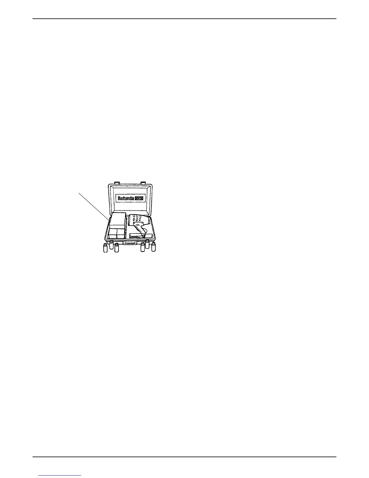
Fluorescent Oil Additive Method
Use a 12 Volt Master UV Diagnostic Inspection Kit, such
as the Rotunda Oil Leak Detector Y112-R0021 or
equivalent, to perform the following procedure for oil
leak diagnosis.
1. Clean the engine with a suitable solvent to remove
all traces of oil.
2. Drain engine oil crankcase and refill with
recommended oil, premixed with Diesel Engine Oil
Dye 164-R3705 meeting Ford specification ESE-
M9C103-B1 or equivalent. Use a minimum 14.8 ml
(0.5 ounce) to a maximum 29.6 ml (1 ounce) of
fluorescent additive to all engines. If the oil is not
premixed, fluorescent additive must first be added to
crankcase.
3. Run the engine for 15 minutes. Stop the engine and
inspect all seal and gasket areas for leaks using the
12 Volt Master UV diagnostic Inspection Kit. A clear
bright yellow or orange area will identify the leak. For
extremely small leaks, several hours may be
required for the leak to appear.
4. If necessary, pressurize the main oil gallery system
to locate leaks due to improperly sealed, loose or
cocked plugs.
5. Repair all leaks as required.
Pressure Method
The crankcase can be pressurized to locate oil leaks.
The following materials are required to fabricate the tool
to be used:
• air supply and air hose
• air pressure gauge that registers pressure in 4 kPa
(1 psi) increments
• air line shutoff valve
• appropriate fittings to attach the above parts to oil fill,
PCV grommet hole and crankcase ventilation tube
• appropriate plugs to seal any openings leading to
the crankcase
• a solution of liquid detergent and water to be applied
with a suitable applicator such as a squirt bottle or
brush
Fabricate the air supply hose to include the air line
shutoff valve and the appropriate adapter to permit the
air to enter the engine through the crankcase ventilation
tube. Fabricate the air pressure gauge to a suitable
adapter for installation on the engine at the oil filler
opening.
CAUTION: Use extreme caution when pressurizing
crankcase. Applying air pressure above specified
pressure risks damage to seals, gaskets and core
plugs. Under no circumstances should pressure be
allowed to exceed 27 kPa (4 psi)
Testing Procedure
• Open the air supply valve until the pressure gauge
maintains 20 kPa (3 psi).
• Inspect sealed or gasketed areas for leaks by
applying a solution of liquid detergent and water over
areas for formation of bubbles which indicates
leakage.
Leakage Points - Above Engine
Examine the following areas for oil leakage.
• valve cover gaskets
• intake manifold gaskets
• cylinder head gaskets
• oil filter
• oil pump (if external)
• oil level indicator tube connection
• oil pressure sensor
Leakage Points - Under Engine
• oil pan gaskets
• oil pan sealer
• oil pan rear seal
• engine front cover gasket
Oil Leak
Detector
Y112-R0021