DSG-423 ENGINE
02-45
64.Install oil level indicator tube:
• Tighten to 10 Nm (89 lb-in).
65.Install accessory drive belt.
66.Install any tubes, hoses or components removed or
disconnected.
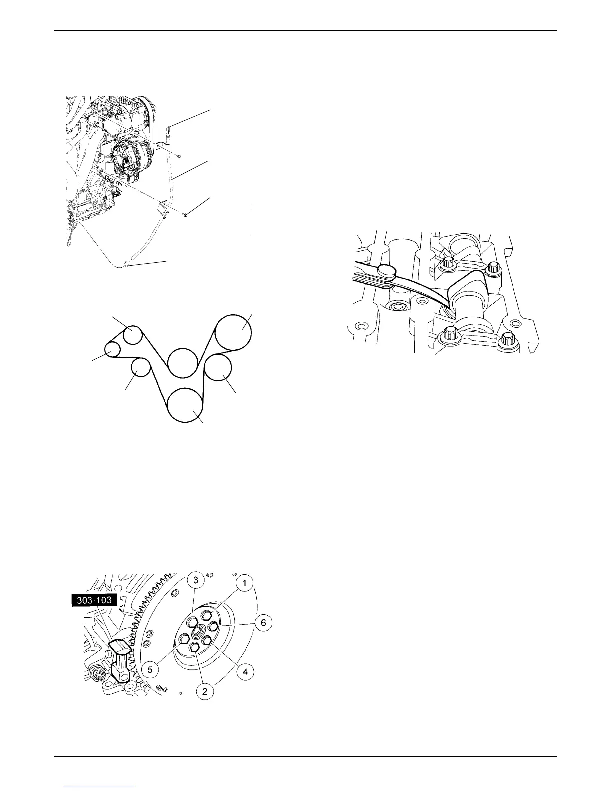
67.Remove engine from engine stand and install
flywheel or flexplate.
68.Using special tool, tighten bolts in the sequence
shown in 3 stages:
• Stage 1: Tighten to 50 Nm (37 lb-ft)
• Stage 2: Tighten to 80 Nm (59 lb-ft)
• Stage 3: Tighten to 112 Nm (83 lb-ft).
69.Lubricate transmission input shaft pilot bearing with
grease.
ADJUSTMENTS
Valve Clearance Check
1. Remove camshaft cover -- Refer to“Camshaft Cover
- Removal” on page 6 of this section.
CAUTION: Turn the engine clockwise only, and use
the crankshaft bolt only.
2. Use a feeler gauge to measure each valve’s
clearance and record its location. A mid range
clearance is most desirable:
• Intake: 0.22-0.28 mm (0.008-0.011 inch)
• Exhaust: 0.27-0.33 mm (0.010-0.013 inch)
NOTE: Measure each valve’s clearance at base circle
with lobe pointed away from the tappet, before
removing camshafts. Failure to measure all clearances
prior to removing camshafts will necessitate repeated
removal and installation and wasted labor time.
3. Select tappets and mark location using the following
formula:
• tappet thickness = measured clearance, plus
base tappet thickness, minus most desirable
thickness.
NOTE: If any tappets do not measure within
specifications, install new tappets in those locations --
Refer to“Valve Tappet - Replacement” on page 18 of
this section.
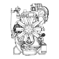
Oil Level
Indicator
Tube
Bolt
O-ring
Power Steering
Crankshaft
Coolant Pump
Fan
Tensioner
Idler
Generator