Maintenance 4. Cable
G10 / G20 Rev.20 123
Turn ON the Controller and change the motor to OFF status (MOTOR OFF).
the brake release switch to let the shaft down.
Be sure to keep enough
space and prevent the
end effector hitting any peripheral equipment.
both Joints #3 and #4. When the brake release
switch is pressed, the brakes
for both Joints #3 and #4 are released simultaneously.
Be careful of the shaft falling
or rotation while the brake release switch
because it may be lowered by the weight of an end effector.
and disconnect the power cable and signal cable connectors
from thee controller
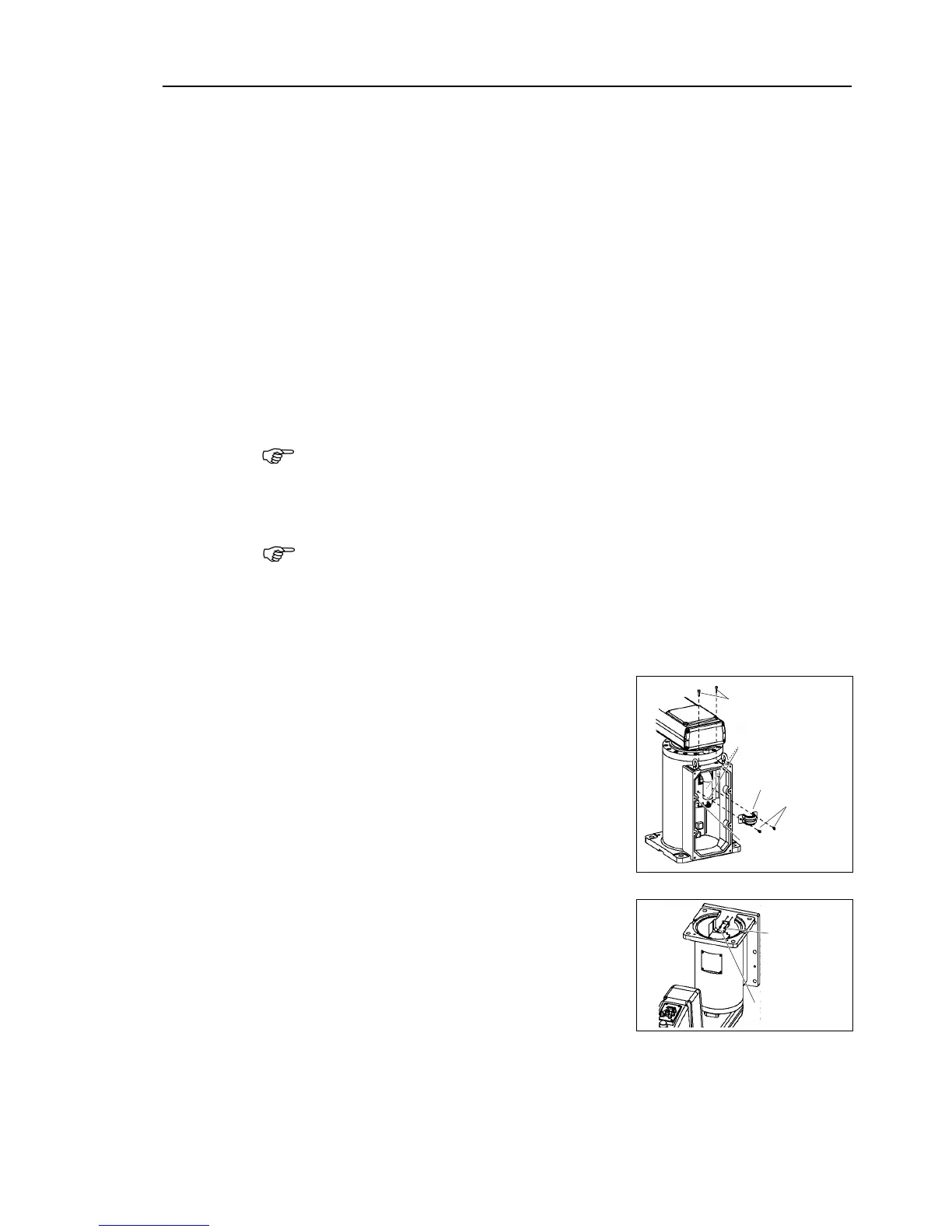
Remove the connector plate.
For details, refer to Maintenance: 3.4 Connector Plate.
Connect the spare battery to connector XB11.
- The position data of Joint #1 motor is stored with the battery on Arm #2
Connect the spare battery otherwise the Joint #1 position data will be lost.
Disconnect the air tubes, ground wire, D
sub cable, and seven connectors (X10, X20,
X30, X111, X121, X131,
XB10) connected to the connector plate (inner side).
Remember the cable layout so that the cables can be reconnected
The procedure of step (7) differs by mounting types.
Follow the corresponding procedure.
hen using Table Top mounting type or Ceiling mounting type
Remove the saddle part mounting cables
(7)-2 Remove the spring plate.
(7)-3 Cut off the two wire ties binding cables.
hen using Wall mounting type
(7)-1 Remove the ground plate.

 Loading...


