Maintenance 4. Cable
G10 / G20 Rev.20 125
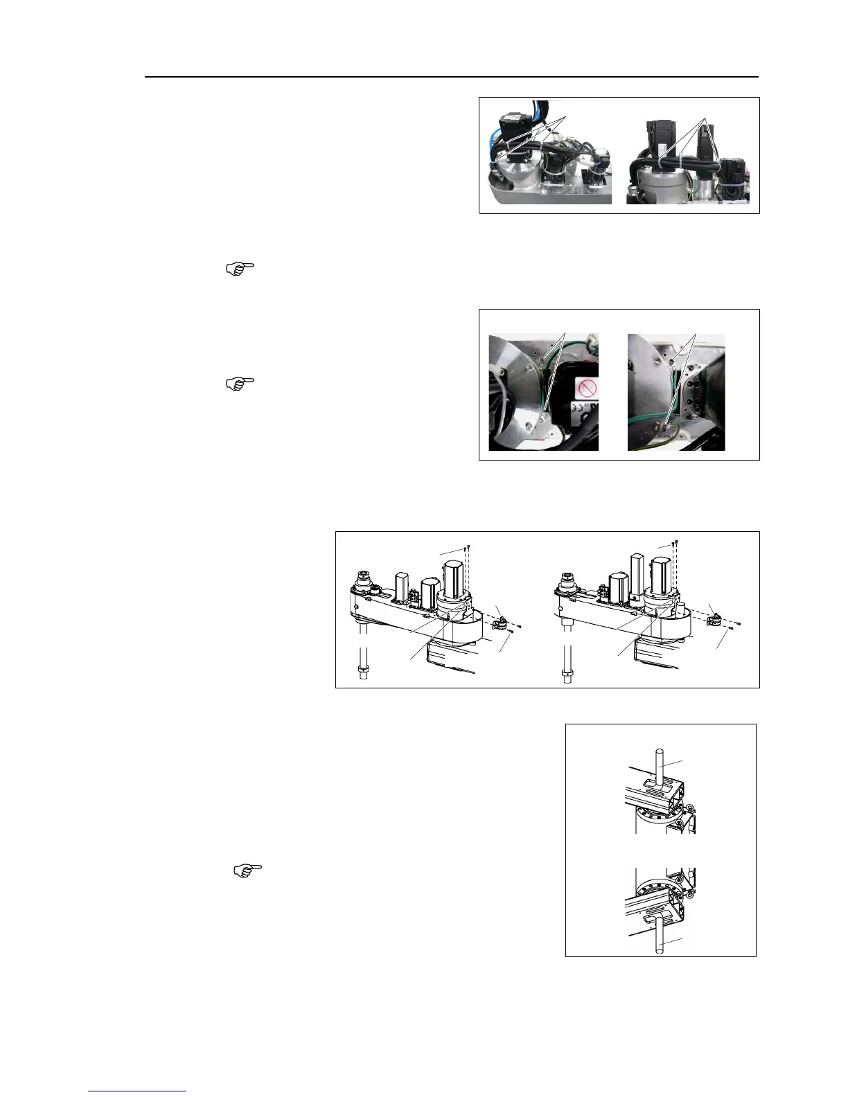
Cut off the wire tie binding
cables
Remove the 11 connectors on the
Arm side.
X21, X22, X31, X32, X33, X41,
X42, X61, X221, X231, X241
keep the connectors excluding X61 of the battery board connected at
cables replacement. Otherwise, the motor will lose position
Remove the ground terminals
mounted to Arm
Record the connection terminal
and the connection point before
disconnect the ground terminal.
G10/G20-***S*/C*: 3 terminals
G10/G20-***D*/P*: 3 terminals
Remove the saddle part mounting cables inside Arm #2.
two wire tie binding cables.
isconnect the Base side cables from Arm #1.
Table Top mounting
: Disconnect from the upper part of Arm #1
Wall mounting / Ceiling mounting
: Disconnect t from the lower part of Arm #1
disconnecting the cables, first, disconnect
smaller connectors in order.
disconnect the cables forcibly.
Otherwise, connectors may be stuck,
disconnected, or connector pins may fall off.

 Loading...


