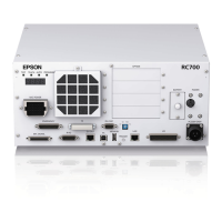
Functions 2. Part Names and Functions
RC700 Series Rev.3 89
(8) Encoder Voltage Adjustment Switch
Use this switch to adjust voltage according to length of M/C cable. (adjusted as a
factory default)
Wrong setting may result in Robot system malfunction. Do not change the switch.
(9) M/C SIGNAL connector
This connector is used for signals such as the Manipulator’s motor encoders, etc.
Connect the Manipulator’s dedicated signal cable.
(10) R-I/O connector
This connector is for the input signals used for the real time I/O function.
(11) RC700DU: DU OUT Connector / RC700DU-A: OUT Connector
To connect the 2nd Drive Unit:
Use the cable attached for Drive Unit and connect with the DU IN connector of the
2nd Drive Unit.
To connect the 3rd Drive Unit:
Use the cable attached for Drive Unit and connect with the DU IN connector of the
3rd Drive Unit.
(12) RC700DU: DU IN Connector / RC700DU-A: IN Connector
For the 1st Drive Unit:
Use the cable attached for Drive Unit and connect with the DU OUT connector of
the Control Unit.
For the 2nd Drive Unit:
Use the cable attached for Drive Unit and connect with the DU OUT connector of
the 1st Control Unit.
For the 3rd Drive Unit:
Use the cable attached for Drive Unit and connect with the DU OUT connector of
the 2nd Control Unit.
(13) RC700DU / RC700DU-A No. Setting Switch
This switch indicated the Drive Unit number.
For details, refer to 5. Drive Unit Setup.
(14) I/O connector
This connector is used for input/output device. There are 24 inputs and 16 outputs.
For details, refer to 13. I/O Connector.
(15) AC IN
The cable for 200VAC power input.
For details, refer to 3.3.2 AC Power Cable.
(16) Drive Unit Number label
The serial number of the Drive Unit is indicated.

 Loading...