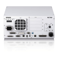
Functions 2. Part Names and Functions
88 RC700 Series Rev.3
Drive Unit
RC700DU
/ RC700DU-A
(1) Signature label (top panel)
The serial number of the Drive Unit and other information are shown.
(2) LED
The LED indicates current operation mode (RUN, AUTO, ERROR/E-STOP).
For details, refer to 2.1 LED & Seven Segment LED
(3) M/C POWER connector
A connector for the Manipulator power source.
Connect the dedicated power cable attached to the Manipulator.
(4) Fan Filter
A protective filter is installed in front of the fan to filter out dust.
Check the condition of the filter regularly and clean it when necessary. A dirty filter
may result in malfunction of the robot system due to temperature rise of the Drive
Unit. For inspection, cleaning, and replacement, refer to RC700 series Maintenance
Manual 4.1 Fan Filter, 4.2 Fan.
(5) POWER switch
Turns ON or OFF the Drive Unit.
(6) Connection Check label
The details of the Manipulator to be connected are recorded
on the label as shown in the right. The label indicates the
Manipulator model and Manipulator serial number.
(7) EMERGENCY connector
This connector is used for input/output from/to Emergency Stop and Safety Door
switches. For details, refer to the 11. EMERGENCY.

 Loading...