Functions 3. Installation
RC700 Series Rev.3 107
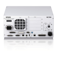
Terminal block for 200VAC power input to the Drive Unit.
The cable with 50-pin connector on the Drive Unit side.
Connect the POWER connector on
the Manipulator and the M/C POWER
connector on the Drive Unit. Insert the connectors until you hear a “click”.
The cable with 50-pin connector on the Drive Unit side.
Connect the signal cable to the SIGNAL connector on the Manipulator and the M/C
SIGNAL connector on the Drive Unit.
The EMERGENCY connector has inputs to connect the Emergency Stop switch
and the Safety Door switch. For safety reasons, connect proper switches for these
input devices.
For details, refer to the 11. EMERGENCY.
This connector is used for input/output devices of the user.
When there are input/output devices, use this connector.
There are I/O cable (option) and terminal block (option) for the I/O connector.
For details, refer to the 13. I/O Connector.
This connector is used for connecting with input signals necessary for real time I/O
function.
For details, refer to the 15. R-I/O Connector.
For the 1
st
Drive Unit:
Use the cable attached for Drive Unit and connect with the DU OUT connector of
the Control Unit.
For the 2
nd
Drive Unit:
Use the cable attached for Drive Unit and connect with the DU OUT connector
of the 1
st
Control Unit.
For the 3
rd
Drive Unit:
Use the cable attached for Drive Unit and connect with the DU OUT connector
of the 2
nd
Control Unit.
To connect the 2
nd
Drive Unit:
Use the cable attached for Drive Unit and connect with the DU IN connector of the
2
nd
Drive Unit.
To connect the 3
rd
Drive Unit:
Use the cable attached for Drive Unit and connect with the DU IN connector of
the 3
rd
Drive Unit.
* Be sure not to connect anything to this connector when using only one Drive
Unit. Also, when using the 3
rd
Drive Unit, do not connect anything to this
nd

 Loading...