Rev. A Disassembly and Assembly 2-9
Confidential
TM-H6000/H6000P Service Manual
Figure 2-9
Pre-assembly of the H. P. Detector Assembly
1. Solder lead wires L, M, N in that order to the H. P. detector assembly.
Note:
Check that the soldering is secure.
2. Attach the H. P. detector assembly to the carriage sub assembly frame. Keep the H. P.
detector assembly lead wire from being pinched between the carriage sub assembly frame.
3. Install the slip print head unit (Eb) into the carriage assembly. Insert the flexible plastic
cable (FPC) into the intermediate circuit board connector and position with the two carriage
assembly pins to attach. At this time, insert the FPC so that it is below the rack.
4. Attach the nose guide to the carriage assembly. Align the three nibs on the carriage
assembly tip and insert.
5. Solder the four carriage motor cables and the three H. P. detector assembly cables to the
intermediate circuit board assembly.
676
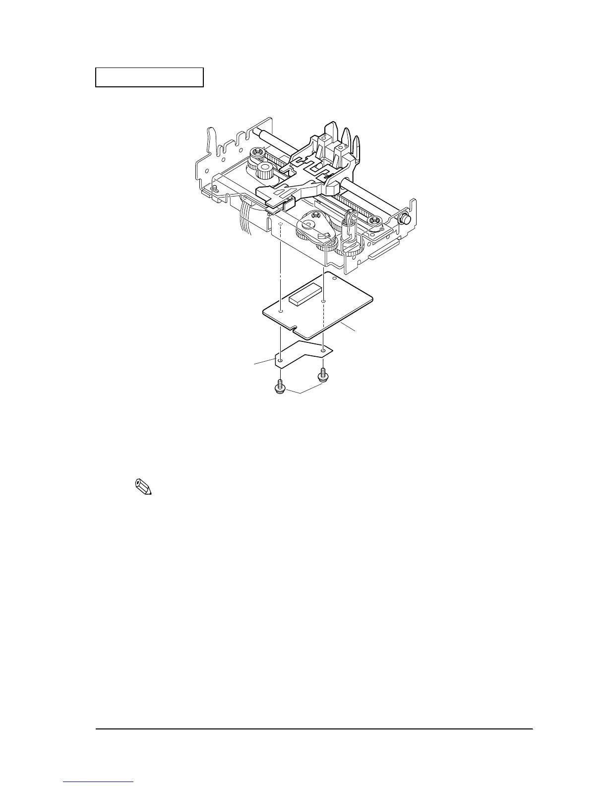
Intermediate circuit board
assembly
726
Intermediate circuit
board cover
731 screw(C.P.S-tite(P4),3X6)
 Loading...


