Rev. C Setup 3-1
TM-H6000III Technical Reference Guide
Chapter 3
Setup
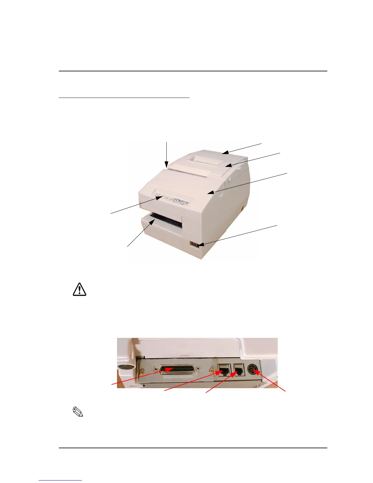
3.1 Part Name and Basic Operation
3.1.1 Part Names
3.1.2 Connectors
WARNING:
Do not connect a telephone line to the drawer kick-out connector or the display module connector;
otherwise the printer and the telephone line may be damaged.
You can connect up to four cables to the printer. They all connect to the connector panel (on the
bottom rear of the printer), which is shown below.
Note:
This illustration shows the serial interface model. The parallel interface connector looks slightly different.
roll paper cover
unit cover
front cover
power switch
control panel
Slip entrance
Validation entrance
(validation model only)
interface
connector
display module
connector
drawer kick-out
connector
power supply
connector

 Loading...


