Rev. C Setup 3-13
TM-H6000III Technical Reference Guide
3.3.5.2 Parallel Interface Models
1. Press the connector on the end of the interface cable firmly into the interface connector on
the connector panel.
2. Press down the clips on either side of the connector to lock it in place.
3. For interface cables equipped with a ground line, attach the ground line to the screw hole
marked "FG" on the printer.
4. Connect the other end of the interface cable to the host computer.
3.3.5.3 USB Interface Models
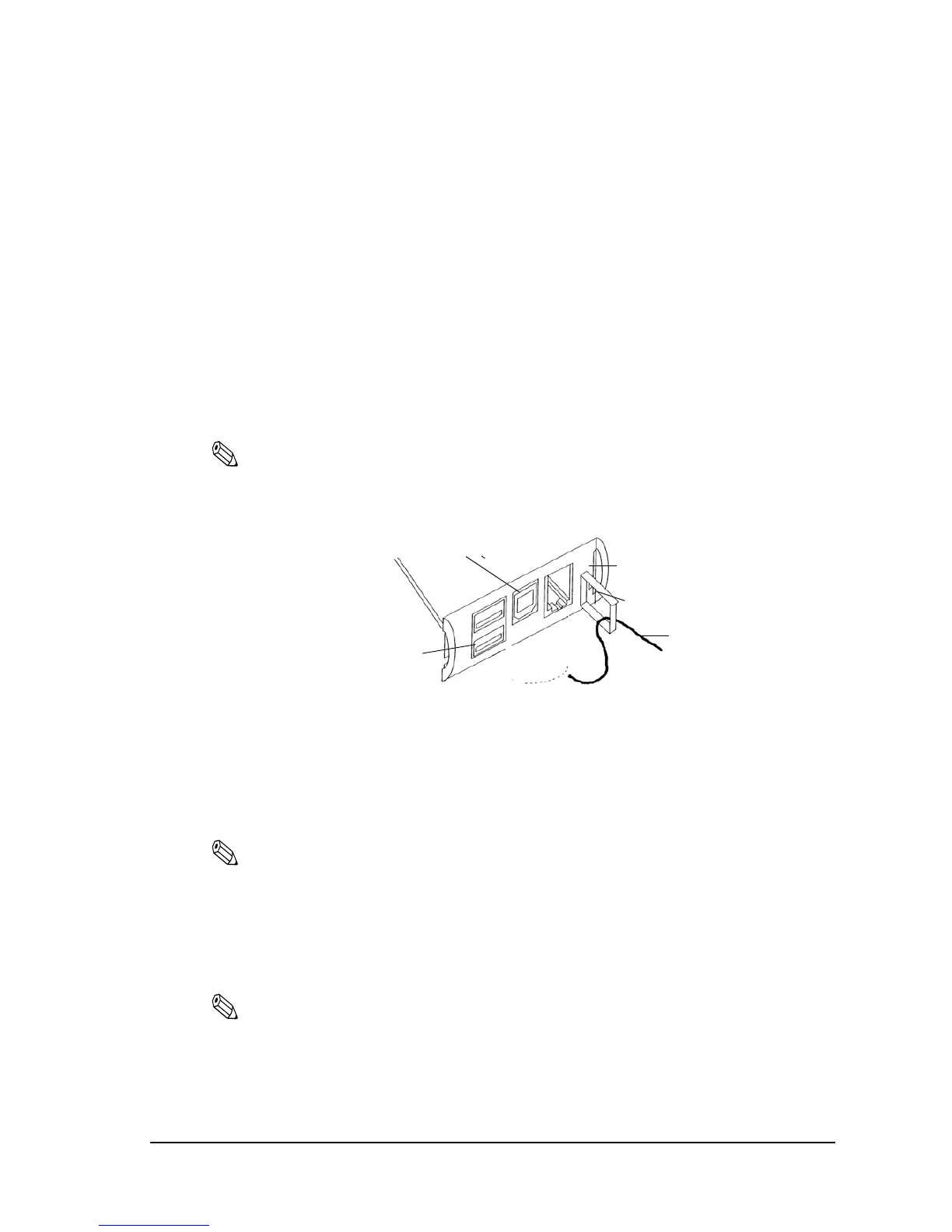
1. Attach the locking wire saddle at the location shown in the figure below.
2. Hook the USB cable through the locking wire saddle, as shown in the figure below.
Note:
Hooking the USB cable through the locking wire saddle, as shown in the figure below, will prevent the
cable from coming unplugged.
Attaching locking wire saddle
3. Connect the USB cable from the host computer to the USB upstream connector.
4. For models that have the UB-U01III installed, a maximum of two USB devices can be
connected to the USB downstream connector.
Note:
The UB-U01III serves as a bus power-supply hub. Therefore, it is important to note that bus power
supply hubs (including the UB-U01III) and bus power supply functions with power dissipation of
100 mA or more cannot be connected directly to the printer. (A UB-U02III can be directly connected
to a UB-U01III hub.)
5. Install the UB-U01III/U02III device driver on the host computer.
Note:
The USB driver is downloadable from the web site. “Downloading Drivers, Utilities, and Manuals”
on page 2-8
USB upstream connector
Locking wire saddle
USB cable
DM connector
USB downstream connector
(Only for the USB HUB: UB-U01III)
UB-BOARD

 Loading...


