TORCH DATA 100i-400i 140 Manual 0560956430
Mild Steel
Flow Rates (SLPM / SCFH)
100A
O₂ Air
Preow
- / - 38 / 81
O₂ Plasma / Air Shield
Culow
16 / 35 27 / 58
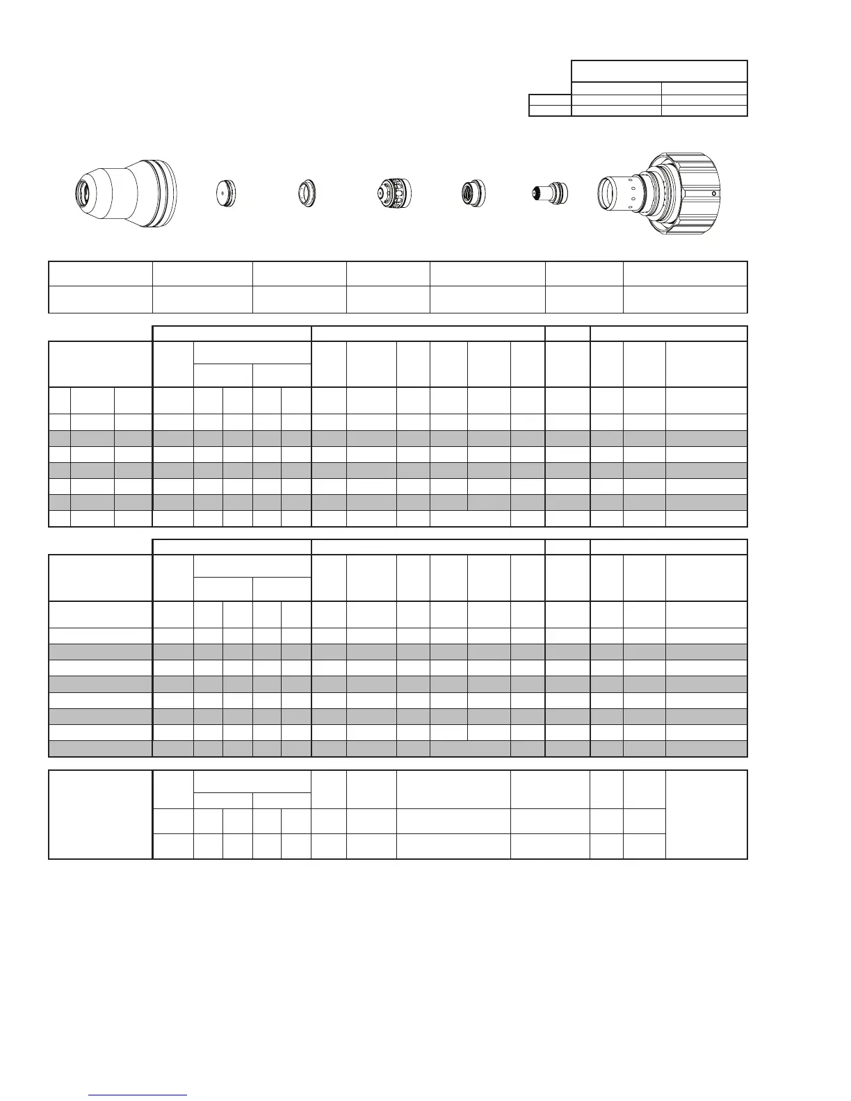
Electrode
Shield Cap
Tip
Shield Gas
Distributor
Plasma Gas
Distributor
Cartridge
Shield Cup
This Art Is For Reference ONLY
Art # A-07958_AB
Shield Cup Shield Cap
Shield Gas
Distributor
Tip Plasma Gas Distributor Electrode Cartridge
0559211201 0559210044 0559210071 0559210024 0559210061 0559210003 0559211200
Manual Gas Control Advanced Torch Height Control (THC) Basic THC CNC Control
Material
Thickness
Pre Flow
Pressure
(Air)
Cut Flow Rates / Pressures
Arc
Voltage
Cut Height
THC
Pierce
Delay
Pierce
Ignion
Height
Elevaon
Height
Control
Delay
Pierce
Height
without
Elevaon
Travel
Speed
CNC
Moon
Delay
Max Kerf Width
@ Rec. Speed
Plasma (O₂) Shield (Air)
ga (in) inch (psi) Ball (psi) Ball (psi) (Volts) (in) ±0.005 (sec) (in) (in) (sec) (in) (ipm) (sec) (in)
10 - 0.135 40 55 120 80 120 138 0.070 0.2 0.125 0.120 0.6 0.200 280 0.2 0.065
- 3/16 0.188 40 55 120 80 120 140 0.090 0.2 0.125 0.120 0.6 0.200 190 0.2 0.070
- 1/4 0.250 40 55 120 80 120 141 0.090 0.3 0.125 0.120 0.5 0.200 145 0.3 0.078
- 3/8 0.375 40 55 120 80 120 143 0.110 0.4 0.150 0.150 0.4 0.250 90 0.4 0.085
- 1/2 0.500 40 55 120 80 120 147 0.120 0.6 0.200 0.150 0.4 0.300 60 0.6 0.097
- 5/8 0.625 40 55 120 80 120 148 0.120 0.8 0.250 0.200 0.4 0.350 50 0.8 0.100
- 3/4 0.750 40 55 120 80 120 157 0.150 3.5 Edge Start 0.4 Edge 25 2.0 0.125
Manual Gas Control Advanced Torch Height Control (THC) Basic THC CNC Control
Material
Thickness
Pre Flow
Pressure
(Air)
Cut Flow Rates / Pressures
Arc
Voltage
Cut Height
THC
Pierce
Delay
Pierce
Ignion
Height
Elevaon
Height
Control
Delay
Pierce
Height
without
Elevaon
Travel
Speed
CNC
Moon
Delay
Max Kerf Width
@ Rec. Speed
Plasma (O₂) Shield (Air)
(mm) (Bar) Ball (Bar) Ball (Bar) (Volts) (mm) ±0.1 (sec) (mm) (mm) (sec) (mm)
(mm/
min)
(sec) (mm)
4 2.8 55 8.3 80 8.3 139 2.0 0.2 3.2 3.0 0.6 5.1 6140 0.2 1.7
5 2.8 55 8.3 80 8.3 140 2.3 0.2 3.2 3.0 0.6 5.1 4660 0.2 1.8
6 2.8 55 8.3 80 8.3 141 2.3 0.3 3.2 3.0 0.5 5.1 3940 0.3 1.9
8 2.8 55 8.3 80 8.3 142 2.6 0.4 3.5 3.4 0.4 5.7 2960 0.4 2.1
10 2.8 55 8.3 80 8.3 144 2.8 0.4 4.0 3.8 0.4 6.5 2170 0.4 2.2
12 2.8 55 8.3 80 8.3 146 3.0 0.6 4.8 3.8 0.4 7.3 1690 0.6 2.4
15 2.8 55 8.3 80 8.3 148 3.0 0.7 6.0 4.7 0.4 8.5 1340 0.7 2.5
20 2.8 55 8.3 80 8.3 157 3.8 4.3 Edge Start 0.4 Edge 640 2.4 3.2
Marking
Pre Flow
Pressure
(N₂)
Marking Flow Rates /
Pressures
Arc
Voltage
Marking
Height
Pierce Ignion Height
THC and CNC
Delay
Control
Delay
Travel
Speed
Marking quality
degrades as
thickness
decreases.
17A Arc Current
Plasma (N₂) Shield (N₂)
Burn-through may
happen for thicknesses
< 1/16” (0.063”) /
1.6 mm.
(psi) /
(Bar)
Ball
(psi) /
(Bar)
Ball
(psi) /
(Bar)
(Volts)
(in) ±0.005 /
(mm) ±0.1
(in) ±0.005 / (mm) ±0.1 (sec) (sec)
(ipm) /
(mm/ min)
20 / 1.4 50
40 /
2.8
100
80 /
5.5
144 0.120 / 3.0 0.120 / 3.0 0 0.4
300 /
7620
BOLD TYPE indicates maximum piercing parameters. BOLD ITALIC indicates edge starts only.