Manual 0560956430 181 TORCH DATA 100i-400i
Aluminum
Flow Rates (SLPM / SCFH)
300A
H35 N₂
Preow
- / - 74 / 156
H35 Plasma / N₂ Shield
Culow
44 / 93 51 / 107
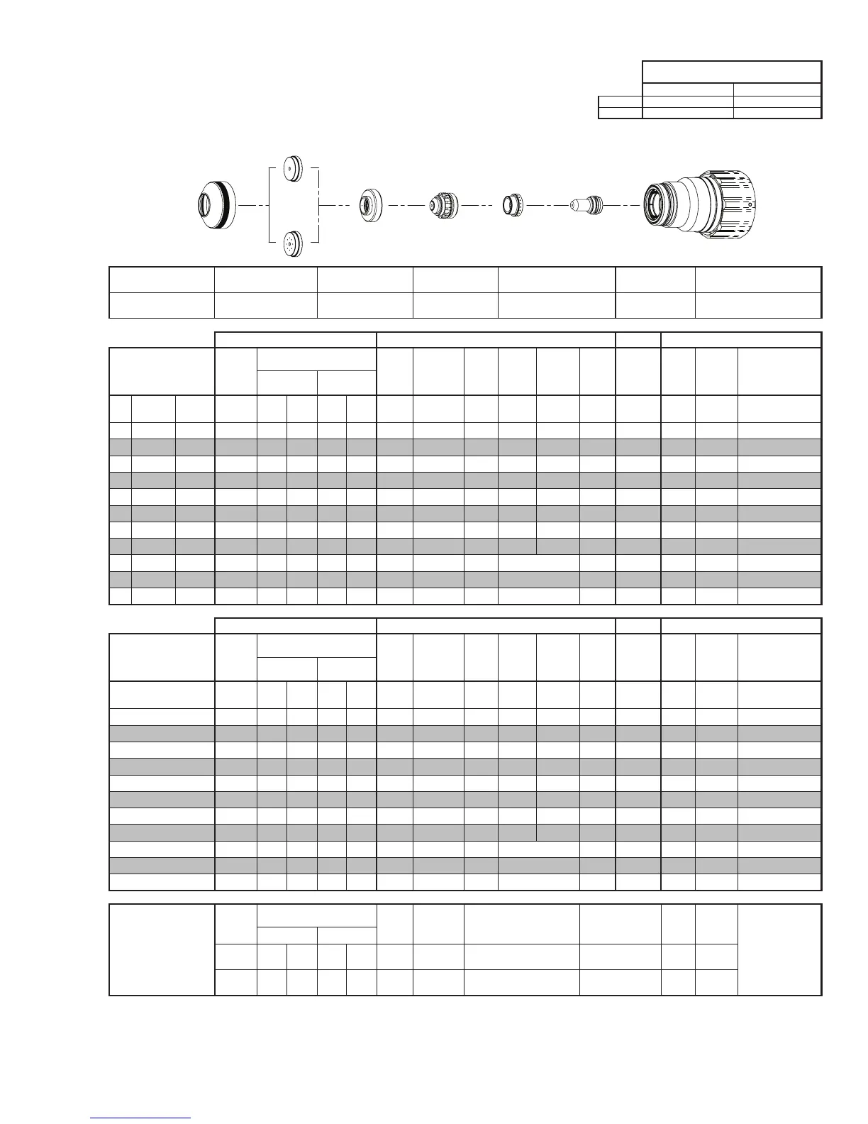
Electrode
Shield Retainer
Tip
Art # A-08567_AB
Plasma Gas
Distributor
Cartridge Assembly
This Art Is For Reference ONLY
Shield Cap
Shield Gas
Distributor
Shield Retainer Shield Cap
Shield Gas
Distributor
Tip Plasma Gas Distributor Electrode Cartridge
0559211211
< 1” /
0559210151
≥ 1” / 0559210153
0559210082 0559210130 0559210061 0559210111 0559211300
Manual Gas Control Advanced Torch Height Control (THC) Basic THC CNC Control
Material
Thickness
Pre Flow
Pressure
(N₂)
Cut Flow Rates / Pressures
Arc
Voltage
Cut Height
THC
Pierce
Delay
Pierce
Ignion
Height
Elevaon
Height
Control
Delay
Pierce
Height
without
Elevaon
Travel
Speed
CNC
Moon
Delay
Max Kerf Width
@ Rec. Speed
Plasma (H35) Shield (N₂)
ga (in) inch (psi) Ball (psi) Ball (psi) (Volts) (in) ±0.005 (sec) (in) (in) (sec) (in) (ipm) (sec) (in)
- 1/4 0.250 20 120 100 NA 120 163 0.400 0.1 0.300 0.250 0.5 0.400 300 0.1 0.182
- 3/8 0.375 20 120 100 NA 120 163 0.400 0.2 0.300 0.250 0.4 0.400 275 0.2 0.186
- 1/2 0.500 20 120 100 NA 120 153 0.300 0.4 0.300 0.250 0.3 0.400 210 0.3 0.174
- 5/8 0.625 20 120 100 NA 90 160 0.300 0.6 0.250 0.300 0.2 0.350 140 0.4 0.169
- 3/4 0.750 20 120 100 NA 90 159 0.300 0.8 0.250 0.300 0.2 0.350 110 0.5 0.172
- 7/8 0.875 20 120 100 NA 90 162 0.300 1.0 0.300 0.250 0.2 0.400 95 0.6 0.183
- 1 1.000 20 120 100 NA 120 165 0.350 1.2 0.350 0.300 0.2 0.450 85 0.7 0.190
- 1 1/4 1.250 20 120 100 NA 120 168 0.400 1.6 0.400 0.400 0.2 0.500 60 0.8 0.205
- 1 1/2 1.500 20 120 100 NA 120 177 0.400 1.5 Edge Start 0.2 Edge 45 1.0 0.215
- 1 3/4 1.750 20 120 100 NA 120 182 0.400 0.4 Edge Start 0.2 Edge 35 0.4 0.226
- 2 2.000 20 120 100 NA 120 188 0.400 0.4 Edge Start 0.2 Edge 25 0.4 0.215
Manual Gas Control Advanced Torch Height Control (THC) Basic THC CNC Control
Material
Thickness
Pre Flow
Pressure
(N₂)
Cut Flow Rates / Pressures
Arc
Voltage
Cut Height
THC
Pierce
Delay
Pierce
Ignion
Height
Elevaon
Height
Control
Delay
Pierce
Height
without
Elevaon
Travel
Speed
CNC
Moon
Delay
Max Kerf Width
@ Rec. Speed
Plasma (H35) Shield (N₂)
(mm) (Bar) Ball (Bar) Ball (Bar) (Volts) (mm) ±0.1 (sec) (mm) (mm) (sec) (mm)
(mm/
min)
(sec) (mm)
6 1.4 120 6.9 NA 8.3 163 10.2 0.1 7.6 6.4 0.5 10.2 7690 0.1 4.6
8 1.4 120 6.9 NA 8.3 163 10.2 0.2 7.6 6.4 0.4 10.2 7290 0.2 4.7
10 1.4 120 6.9 NA 8.3 162 9.8 0.2 7.6 6.4 0.4 10.2 6740 0.2 4.7
12 1.4 120 6.9 NA 8.3 155 8.2 0.4 7.6 6.4 0.3 10.2 5700 0.3 4.5
15 1.4 120 6.9 NA 6.8 158 7.6 0.5 6.7 7.3 0.2 9.2 4050 0.4 4.3
20 1.4 120 6.9 NA 6.2 160 7.6 0.9 6.7 7.2 0.2 9.3 2680 0.5 4.5
25 1.4 120 6.9 NA 8.0 165 8.7 1.2 8.7 7.5 0.2 11.3 2190 0.7 4.8
30 1.4 120 6.9 NA 8.3 167 9.8 1.5 9.8 9.5 0.2 12.4 1700 0.8 5.1
35 1.4 120 6.9 NA 8.3 175 10.2 1.5 Edge Start 0.2 Edge 1270 1.0 5.3
40 1.4 120 6.9 NA 8.3 178 10.2 1.2 Edge Start 0.2 Edge 1070 0.8 5.5
50 1.4 120 6.9 NA 8.3 187 10.2 0.4 Edge Start 0.2 Edge 670 0.4 5.5
Marking
Pre Flow
Pressure
(N₂)
Marking Flow Rates /
Pressures
Arc
Voltage
Marking
Height
Pierce Ignion Height
THC and CNC
Delay
Control
Delay
Travel
Speed
Marking quality
degrades as
thickness
decreases.
24A Arc Current
Plasma (N₂) Shield (N₂)
Burn-through may
happen for thicknesses
< 1/16” (0.063”) /
1.6 mm.
(psi) /
(Bar)
Ball
(psi) /
(Bar)
Ball
(psi) /
(Bar)
(Volts)
(in) ±0.005 /
(mm) ±0.1
(in) ±0.005 / (mm) ±0.1 (sec) (sec)
(ipm) /
(mm/ min)
15 / 1.0 80
60 /
4.1
NA
90 /
6.2
135 0.120 / 3.0 0.120 / 3.0 0 0.4
300 /
7620
BOLD TYPE indicates maximum piercing parameters. BOLD ITALIC indicates edge starts only.
 Loading...