TORCH DATA 100i-400i 206 Manual 0560956430
Stainless Steel
Flow Rates (SLPM / SCFH)
400A Bevel Cut
H35 N₂
Preow
- / - 207 / 439
H35 Plasma / N₂ Shield
Culow
47 / 100 173 / 367
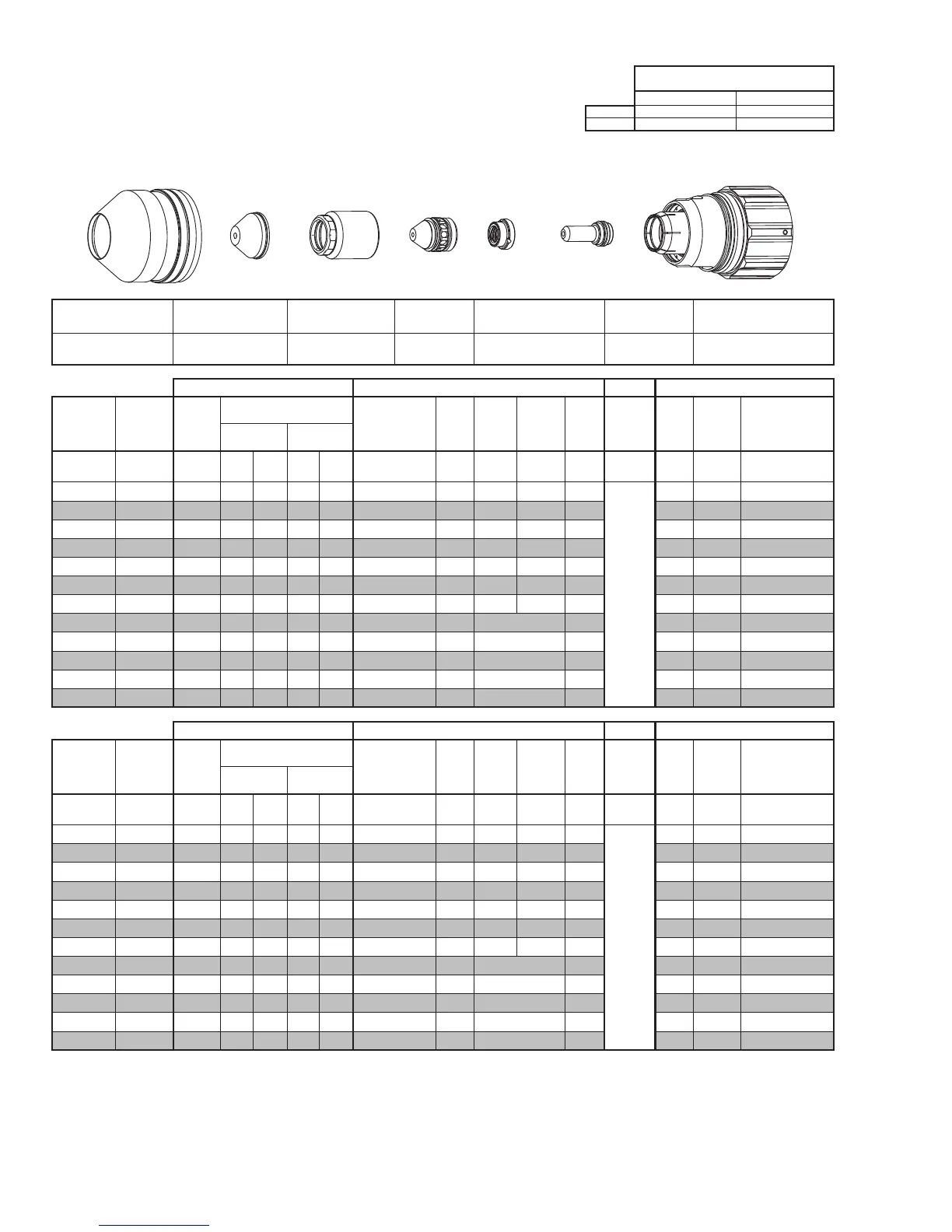
Shield Cup
Shield Cap
Shield Gas
Distributor
Tip
Gas
Distributor
Electrode
Cartridge Assembly
This Art Is For Reference Only
Art# A-10444
Shield Cup Shield Cap
Shield Gas
Distributor
Tip Plasma Gas Distributor Electrode Cartridge
0559211401
≤ 1” / 0559210154
> 1” / 0559210155
0559210083 0559210132 0559210065 0559210112 0559211400
Manual Gas Control Advanced Torch Height Control (THC) Basic THC CNC Control
Eecve
Material
Thickness
Min.
Clearance
Pre Flow
Pressure
(N₂)
Cut Flow Rates / Pressures
Eecve Cut
Height
THC
Pierce
Delay
Pierce
Ignion
Height
Elevaon
Height
Control
Delay
Pierce
Height
without
Elevaon
Travel
Speed
CNC
Moon
Delay
Max Kerf Width
@ Rec. Speed
Plasma (H35) Shield (N₂)
inch (in) (psi) Ball (psi) Ball (psi) (in) (sec) (in) (in) (sec) (in) (ipm) (sec) (in)
0.625 0.080 30 120 100 NA 110 0.350 - 0.600 0.5 0.400 0.400 0.2
Not Recommended without
Elevaon Height
70 0.4 0.230
0.750 0.080 30 120 100 NA 110 0.350 - 0.600 0.6 0.400 0.400 0.2 60 0.5 0.230
1.000 0.080 30 120 100 NA 110 0.350 - 0.600 1.0 0.400 0.500 0.2 45 0.8 0.236
1.250 0.080 30 120 100 NA 110 0.350 - 0.600 1.5 0.400 0.500 0.2 35 1.2 0.235
1.500 0.080 30 120 100 NA 110 0.350 - 0.600 1.8 0.400 0.500 0.2 28 1.3 0.248
1.750 0.080 30 120 100 NA 110 0.350 - 0.600 5.0 0.400 0.750 0.2 20 2.5 0.257
2.000 0.080 30 120 100 NA 110 0.350 - 0.600 10.0 0.400 0.750 0.2 17 5.5 0.268
2.250 0.080 30 120 100 NA 110 0.350 - 0.600 3.0 Edge Start 0.2 12 3.0 0.265
2.500 0.080 30 120 100 NA 110 0.350 - 0.600 3.0 Edge Start 0.2 14 3.0 0.260
3.000 0.080 30 120 100 NA 110 0.350 - 0.600 3.0 Edge Start 0.2 10 3.0 0.275
3.500 0.080 30 120 100 NA 110 0.350 - 0.600 3.0 Edge Start 0.2 5 3.0 0.280
4.000 0.080 30 120 100 NA 110 0.350 - 0.600 4.0 Edge Start 0.2 4 4.0 0.290
Manual Gas Control Advanced Torch Height Control (THC) Basic THC CNC Control
Eecve
Material
Thickness
Min.
Clearance
Pre Flow
Pressure
(N₂)
Cut Flow Rates / Pressures
Eecve Cut
Height
THC
Pierce
Delay
Pierce
Ignion
Height
Elevaon
Height
Control
Delay
Pierce
Height
without
Elevaon
Travel
Speed
CNC
Moon
Delay
Max Kerf Width
@ Rec. Speed
Plasma (H35) Shield (N₂)
(mm) (mm) (Bar) Ball (Bar) Ball (Bar) (mm) (sec) (mm) (mm) (sec) (mm)
(mm/
min)
(sec) (mm)
15 2.0 2.1 120 6.9 NA 7.6 8.9 - 15.2 0.5 10.2 10.2 0.2
Not Recommended without
Elevaon Height
1850 0.4 5.8
20 2.0 2.1 120 6.9 NA 7.6 8.9 - 15.2 0.7 10.2 10.5 0.2 1470 0.5 5.9
25 2.0 2.1 120 6.9 NA 7.6 8.9 - 15.2 1.0 10.2 12.5 0.2 1170 0.8 6.0
30 2.0 2.1 120 6.9 NA 7.6 8.9 - 15.2 1.4 10.2 12.7 0.2 960 1.1 6.0
35 2.0 2.1 120 6.9 NA 7.6 8.9 - 15.2 1.7 10.2 12.7 0.2 800 1.3 6.1
40 2.0 2.1 120 6.9 NA 7.6 8.9 - 15.2 2.8 10.2 14.6 0.2 650 1.7 6.4
50 2.0 2.1 120 6.9 NA 7.6 8.9 - 15.2 9.4 10.2 19.1 0.2 440 5.1 6.8
60 2.0 2.1 120 6.9 NA 7.6 8.9 - 15.2 3.0 Edge Start 0.2 330 3.0 6.7
70 2.0 2.1 120 6.9 NA 7.6 8.9 - 15.2 3.0 Edge Start 0.2 300 3.0 6.8
80 2.0 2.1 120 6.9 NA 7.6 8.9 - 15.2 3.0 Edge Start 0.2 220 3.0 7.0
90 2.0 2.1 120 6.9 NA 7.6 8.9 - 15.2 3.1 Edge Start 0.2 120 3.1 7.1
100 2.0 2.1 120 6.9 NA 7.6 8.9 - 15.2 3.9 Edge Start 0.2 90 3.9 7.3
BOLD TYPE indicates maximum piercing parameters. BOLD ITALIC indicates edge starts only.