MAINTENANCE MANUAL
Page 24-44
Effectivity: All
Edition 2 | Rev. 1
2. MAINTENANCE PRACTICES
A. Switches
Maintenance type: Line
Personnel qualification: Independent verification personnel qualified in accordance with
Part 66 or higher
Recommended tools and material:
Flat screwdriver 1 pc.
NOTE
Removal / installation procedure of switches is identical for the
type 1 PST, 2 PST and as well as for the illuminated rocker
switches type R13-66 and S7 68-72 01.
(1) Removal – switches
(a) Switch the electrical network off and disconnect the battery.
(b) Disconnect the wires from the switch contacts.
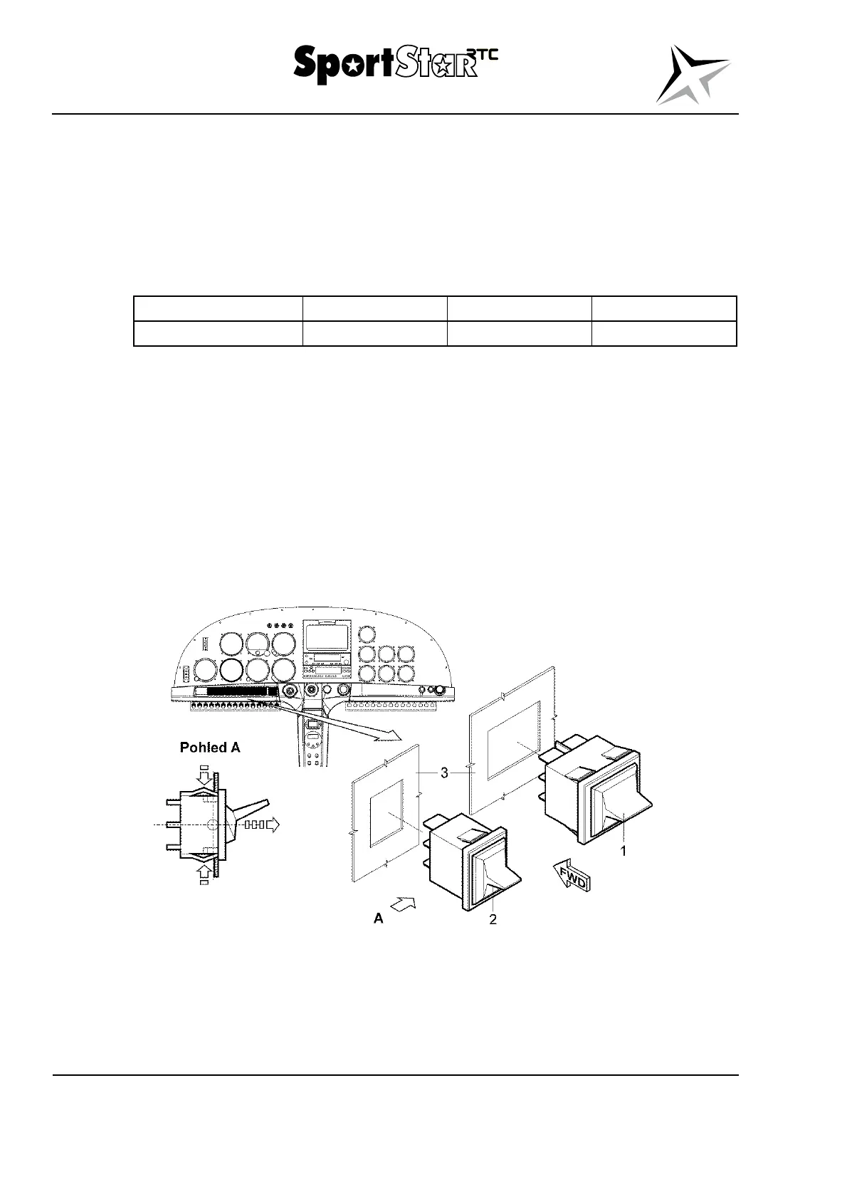
(c) According to detail A, press down the flexible detents in the direction of short
arrows and slide out the switch (1; 2, Fig. 24-18) in the direction of the long arrow
from the instrument panel (3).
Legend to Fig. 24-18
1 Switch 2 PST (master switch) For information:
2 Switch 1 PST 3 Instrument panel
Fig. 24-18 Switches – removal / installation