MAINTENANCE MANUAL
Effectivity: All
Page 25-15
Edition 2 | Rev. 1
(6) Installation – instrument panel
The installation procedure for the instrument panel is described in Section 39-10.
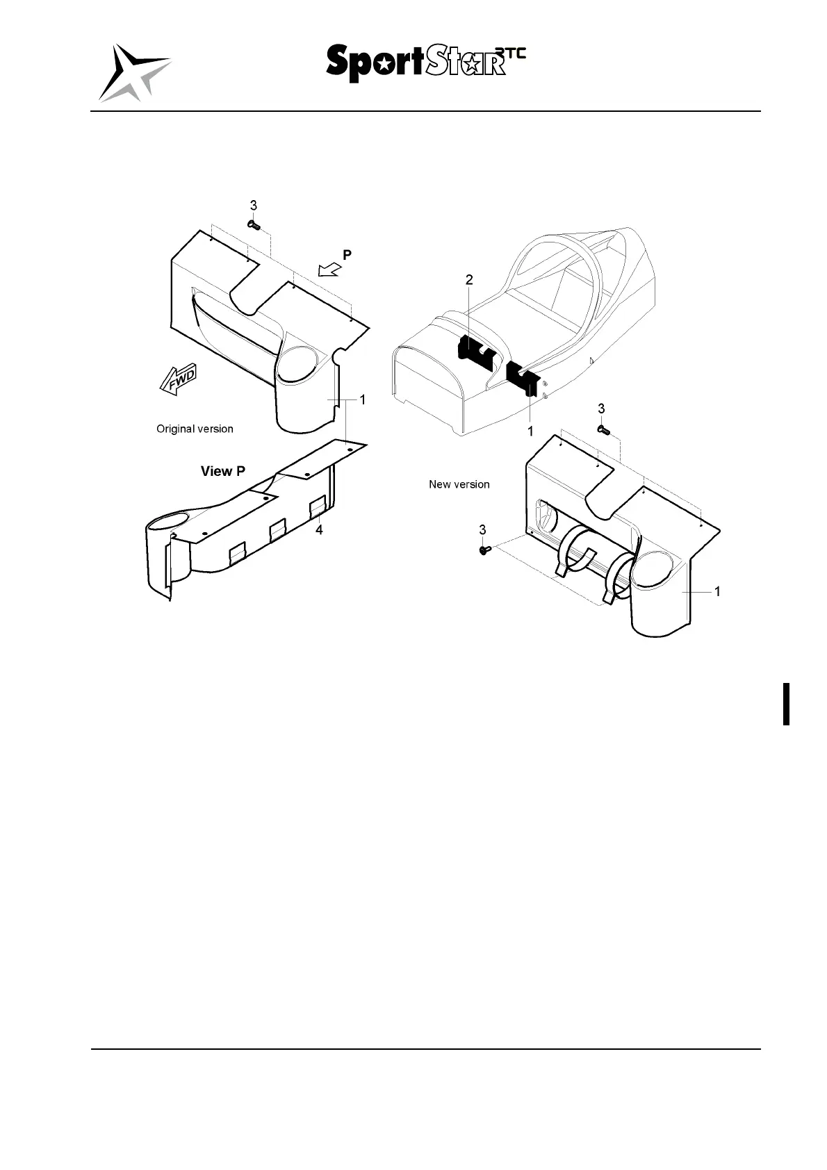
Legend to Fig. 25-5
1 Left control rod cover 3 Bolt M4 (4 pcs. + 4 pcs. / 8 pcs.)
2 Right control rod cover 4 Flexible clamp
Fig. 25-5 Control rod cover - removal / installation
(7) Removal – ledges of the instrument panel
(a) Disable the board network and disconnect the battery.
(b) Before you remove the ledges of the instrument panel, remove the ignition switch
(Section 74-30), throttle and choke control (Section 76-10) and the emergency
parachute system activation handle (if the EPS is installed) (Section 25-60).
(c) Uncsrew and remove the nuts (7, Fig. 25-6) and washers (9) which attach the
ledge (1).
(d) Unscrew the bolts (5) and remove the ledge (1); when removing the ledge, hold the
circuit breakers panel.
(e) Uncsrew and remove the nuts (7) and washers (9) which attach the ledge (3).
(f) Uncsrew the bolts (5) and remove the ledge (3); when removing the ledge, hold the
circuit breakers panel.