MAINTENANCE MANUAL
Page 25-16
Effectivity: All
Edition 2 | Rev. 1
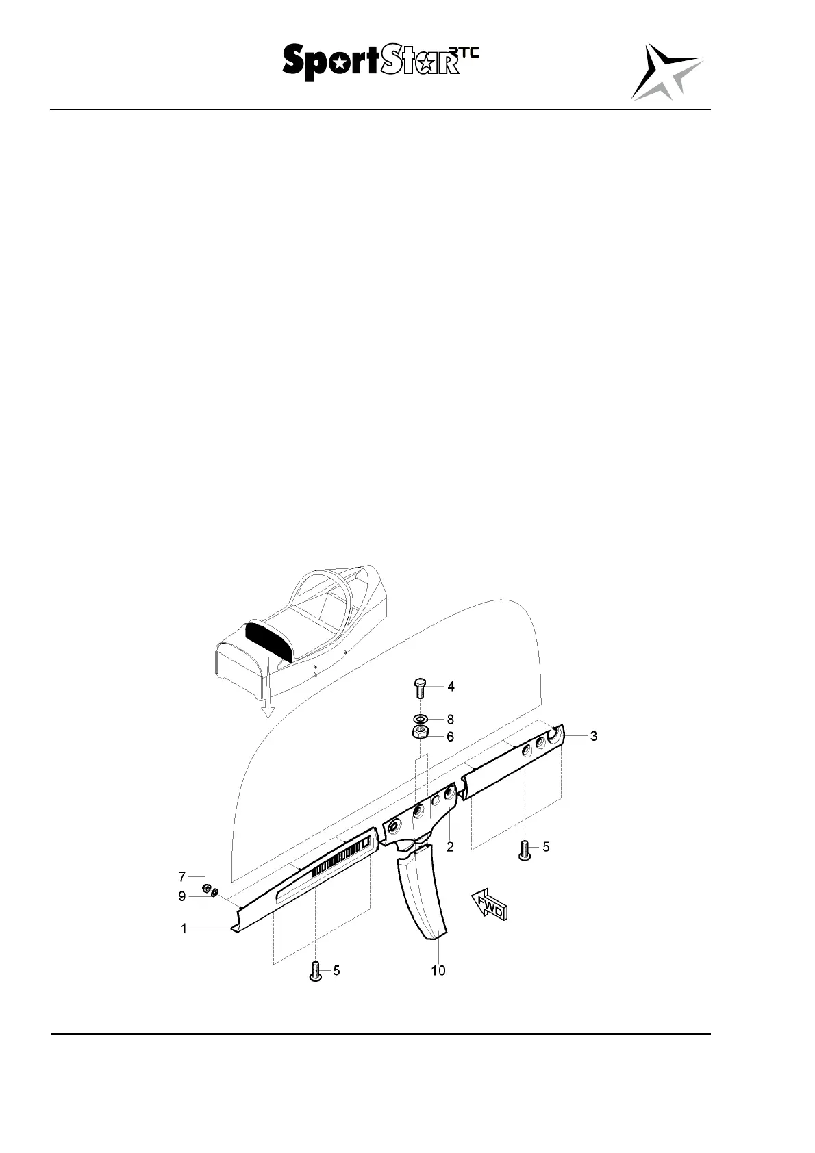
(g) Unscrew and remove the nuts (6), washers (8) and bolts (4) which attach the
central ledge (2) to the central panel (10).
(h) Remove the central ledge (2).
(8) Installation – ledges of the instrument panel
(a) Align the ledge (1, Fig 25-6) with the instrument panel and attach it by the nuts (7)
with washers (9).
(b) Between the instrument panel angle and the ledge (1) insert the circuit breakers
panel and attach them by bolts (5).
(c) Align the ledge (3) with the instrument panel and attach if by the nuts (7) with
washers (9).
(d) Between the instrument panel angle and the ledge (3) insert the circuit breakers
panel and attach them by bolts (5).
(e) Align the central ledge (2) and put the bolts (4) which attach the central ledge into
the central panel (10).
(f) Screw the nuts (6) with washers (8).
(g) Tighten all bolts and nuts.
(h) Install the ignition switch (Section 74-30), throttle and choke control (Section 76-10)
and the emergency parachute system activation handle (if the EPS is installed)
(Section 25-60)
(i) Connect the battery, activate the board network.
Fig. 25-6 Ledges of the instrument panel – removal / installation (page 1 of 2)