MAINTENANCE MANUAL
Effectivity: All
Page 27-5
Edition 2 | Rev. 0
(k) After finishing all the work related to installations and Removal of parts of control
system, check the securing of all the elements in the control systems and their
functionality.
(2) Adjustment / check – adjustment of deflections
Maintenance type: Heavy
Personnel
qualification:
Independent verification personnel qualified in accordance with Part
66 or higher
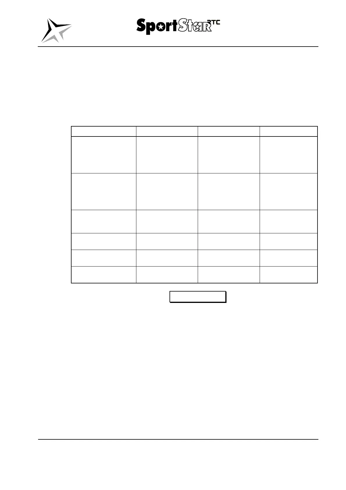
Recommended tools and material:
Item Designation / Size Quantity Note
Protractor - 1 pc. Measurement of
deflections of
ailerons, wing flaps,
elevator and
elevator trim tab.
Measuring jig
(protractor) of VTU
1710S3000401 1 pc. Measurement of
rudder deflections;
it also serves as a
centering jig of
rudder.
Measuring jig
(protractor) of HTU
1710E4008001 1 pc. Measurement of
elevator
deflections.
Strain gauge - 1 pc. Measurement of
stress in cables.
Blocking of elevator - 1 pc. Check of the play in
the control system.
Blocking of ailerons - 1 pc. Check of the play in
the control system.
WARNING
NON-OBSERVANCE OF PRESCRIBED DEFLECTIONS OF
CONTROL SURFACES, WING FLAPS OR TRIM TAB
NEGATIVELY AFFECTS THE FLIGHT CHARACTERISTICS
OF AIRPLANE.
(a) After the replacement of the parts of control system, adjustment of cable tightening
or in other cases where needed, it is necessary to check the deflections of the
control surfaces, wing flaps and the trim tab. If a difference is detected between the
condition on the airplane and the specified values, perform its adjustment.
(b) The procedures for the adjustment of control surfaces, wing flaps and trim tab are
shown in the corresponding Sections that describe individual control systems.
(c) The adjustment values of the deflections of control surfaces, wing flaps and trim tab
are shown in Tab. 27-1.
(d) The length of pull-rod means the distance between the central axes of bearings in
the end pieces of pull-rod or between the central axis of end piece bearing and the
central axis of the hole in the pull-rod fork.