MAINTENANCE MANUAL
Page 32-36
Effectivity: All
Edition 2 | Rev. 1
The brake is provided with two brake pads, one of them serves as a pushing pad and the other
one as a supporting pad. The brake pads are connected by means of two guide pins with the
brake holder. The brake holder is attached on the axis of the main landing gear wheel by means
of four pins. The length of guide pins connecting the brake pads allows the sliding movement
that is necessary for the brake function. By depressing the brake pedal, the pressure in the
brake fluid is generated that is led from the brake pump through the plastic hoses to the brake
cylinder. The pressure of brake fluid shifts the piston that carries the push brake pad and
pushes it onto the brake disk. Simultaneously, the supporting brake pad is pulled from the
opposite side.
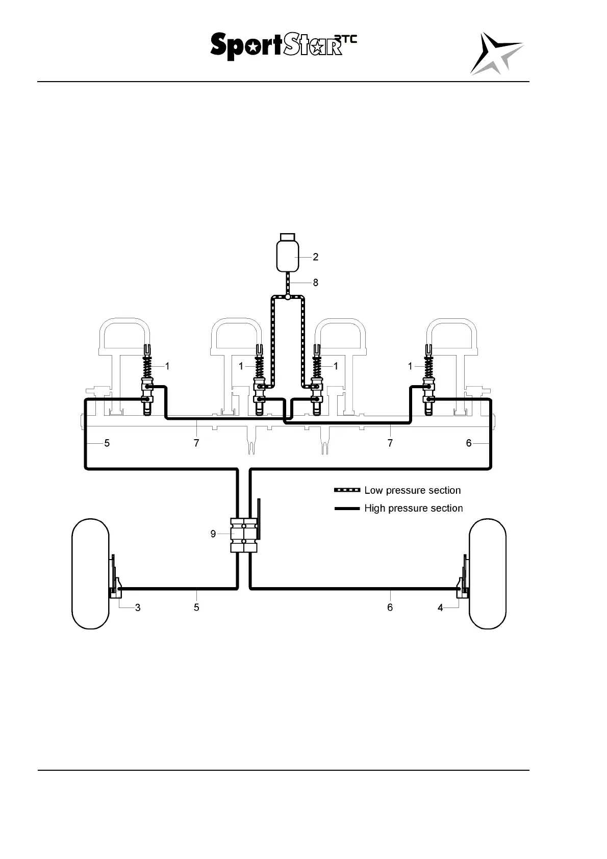
Legend to Fig. 32-13
1 Pump 6 Line of hoses to the right brake
2 Expansion tank 7 Line of connecting hoses
3 Left brake 8 Line of low pressure hoses
4 Right brake 9 Parking brake valve
5 Line of hoses to the left brake
Fig. 32-13 Brake system