MAINTENANCE MANUAL
Effectivity: All
Page 61-7
Edition 2 | Rev. 1
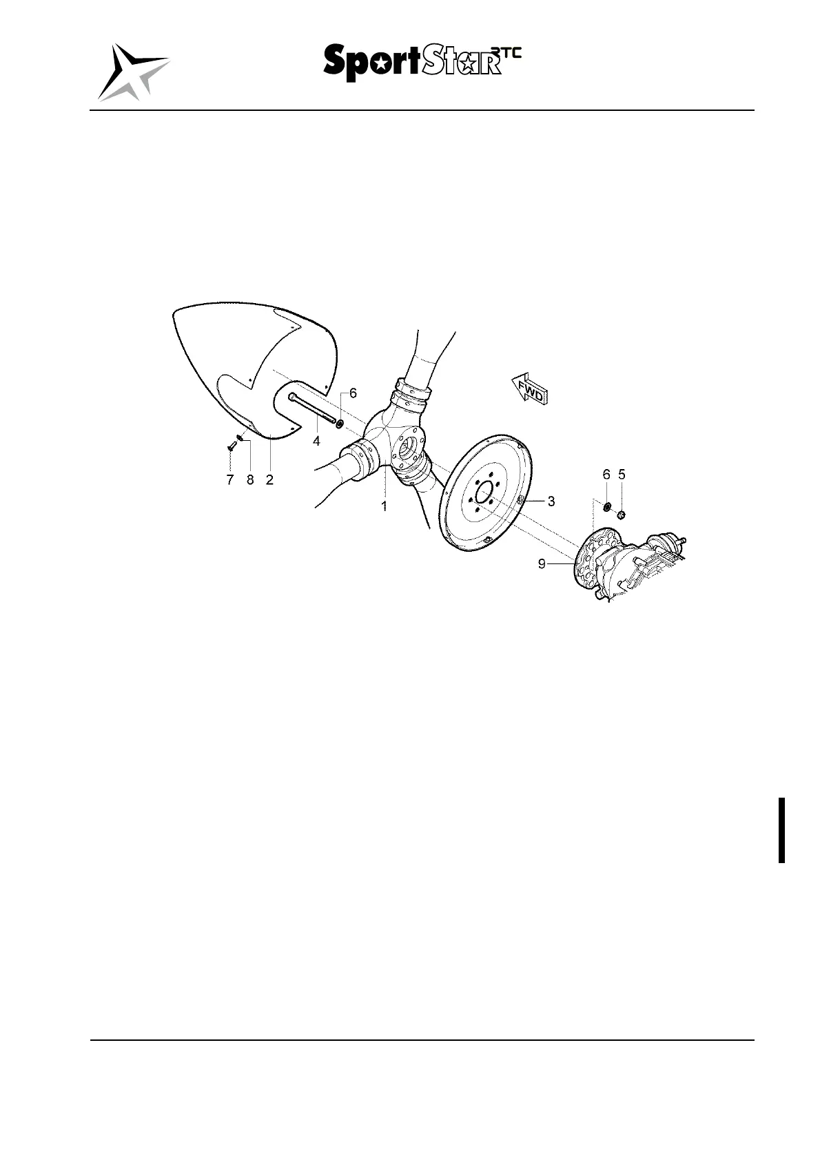
(g) Put the spinner (2) to the backplate (3) in the position marked by red dots on the
circumference. Never install the spinner in other position.
(h) Attach the spinner with the bolts (7) with washers (8); secure the bolts with Loctite
243 adhesive.
(i) Install the engine cowlings (Section 71-10).
(j) Connect the battery, switch the electrical network on.
(k) Start the engine, do the engine test and check engine parameters.
Legend to Fig. 61-1
1 Propeller 6 Washer 8,4 (12 pcs.)
2 Propeller spinner 7 Bolt M4x16 (9 pcs.)
3 Backplate 8 Washer 4,3 (9 pcs.)
4 Bolt M8x105 (6 pcs.) 9 Engine flange
5 Nut M8 (6 pcs.)
Fig. 61-1 Klassic 170/3/R propeller – removal / installation
NOTE
If the external alternator V-belt pulley (Section 24-30) is
installed on the engine flange, the bolts (4, Fig. 61-1) have size
M8x108.