MAINTENANCE MANUAL
Effectivity: All
Page 11-15
Edition 2 | Rev. 1
SERIAL
NO.
PLACARD COLOUR LOCATION FIG.
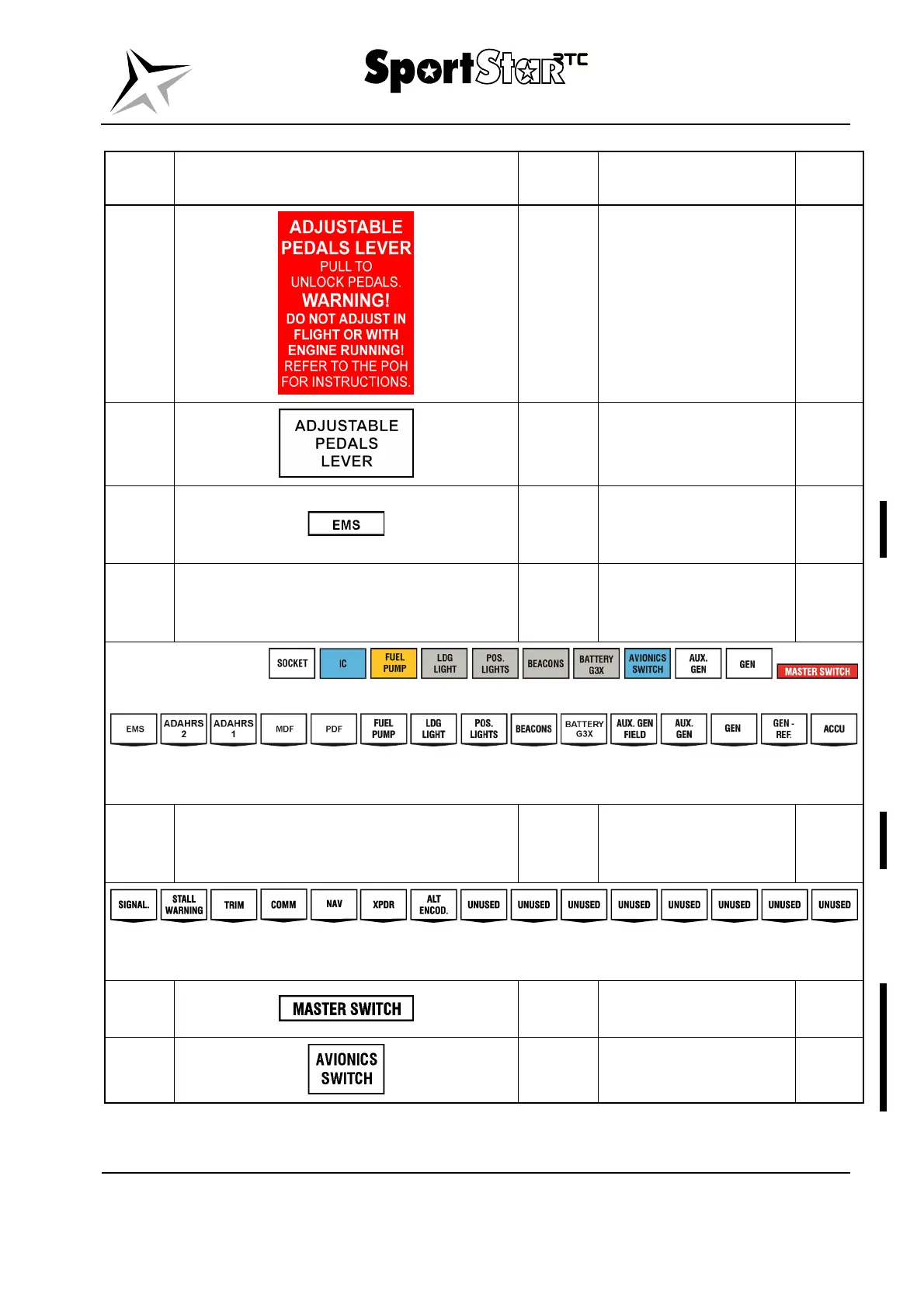
47.
Red
L and R side of the
canopy frame.
11-2
48.
Black
L and R adjustable
pedals lever.
11-2
49.
Black /
white
L part of the instrument
panel at the signalling
light of the EMS.
11-2
50. Various
L part of the instrument
panel at circuit breakers
and circuit breakers.
11-2
NOTE: The above specified layout of the placards applies to the standard design
of the airplane, it may vary depending on the installed equipment.
51.
Black /
white
R part of the instrument
panel at circuit
breakers.
11-2
NOTE: The above specified layout of the placards applies to the standard design
of the airplane, it may vary depending on the installed equipment.
52.
Black /
white
L part of the instrument
panel at master switch.
11-2
53.
Black /
white
L part of the instrument
panel at avionics switch.
11-2