70 05-2019 0073 00
MAIN SWITCH AND FUSE
To access the appliance’s main switch and
line fuse, remove the solid and liquid resi-
due trays.
Important !!!
Inside the appliance, only the parts
remain live.
The protective covers need to be re-
moved after disconnecting the appli-
ance from the power supply.
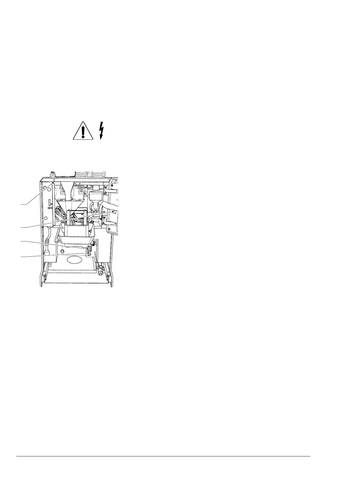
Fig. 48
1. Line fuse
2. Main switch
3. Connectivity switch
4. Magnetic door sensor
CONNECTIVITY SWITCH
When the door is opened, a specic switch
deactivates the appliance’s connectivity
components.
When the door is open, the remote opera-
tion of the functional units and/or the re-
mote control are disabled.
All operations that require the appli-
ance to be live with the door open and
the connectivity functions active, must
EXCLUSIVELY be performed by qual-
-
chine is in this condition.
To activate the connectivity components
(i.e. for a communication test) with the door
open, simply pull the connectivity switch
pin.
If the switch is activated and deactivated
within a short period of time, the appliance
disables the connectivity components; the
appliance will need to be restarted to re-
store these.