Functional characteristics
MIG/MAG welding
40 Item No.: 099-004833-EWM01
5.2.3.6 Accessory components for operating point setting
Accessory component Description
PHOENIX R10 remote control See "Remote controls" chapter
PHOENIX R20 remote control See "Remote controls" chapter
PHOENIX R40 remote control See Phoenix R40 operating instructions
MIG/MAG Powercontrol program torch See "MIG/MAG Powercontrol program torch"
chapter
MIG/MAG Powercontrol2 torch See Powercontrol2 torch operating instructions
PC300.Net PC software See PC300.Net operating instructions
RINT X11 robot interface,
industrial bus interface
See RINTX11 operating instructions
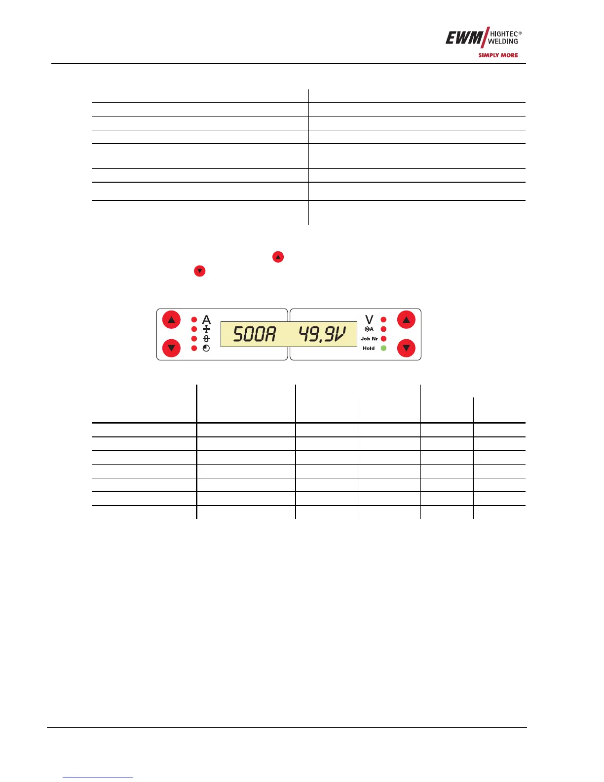
5.2.4 MIG/MAG welding data display
To the left and right of the LCD display on the control there are 2 “arrow keys” on each side for selecting
the welding parameter to be displayed. The
button is used to scroll through the parameters from the
bottom upwards and the
button is used to scroll downwards from the top.
As soon as changes have been made to the settings after welding (display on hold values), the display
switches back to the nominal values.
Figure 5-7
Before welding During welding After welding Parameter
Nominal value Actual value Nominal
value
Hold value Nominal
value
Welding current
z z
z
Material thickness
z
z
z
Wire speed
z z
z
Welding voltage
z z
z
Motor current
z
z
JOB no.
z
Operating time
z