Functional characteristics
Advanced functions on the wire feed unit control
Item No.: 099-004833-EWM01 95
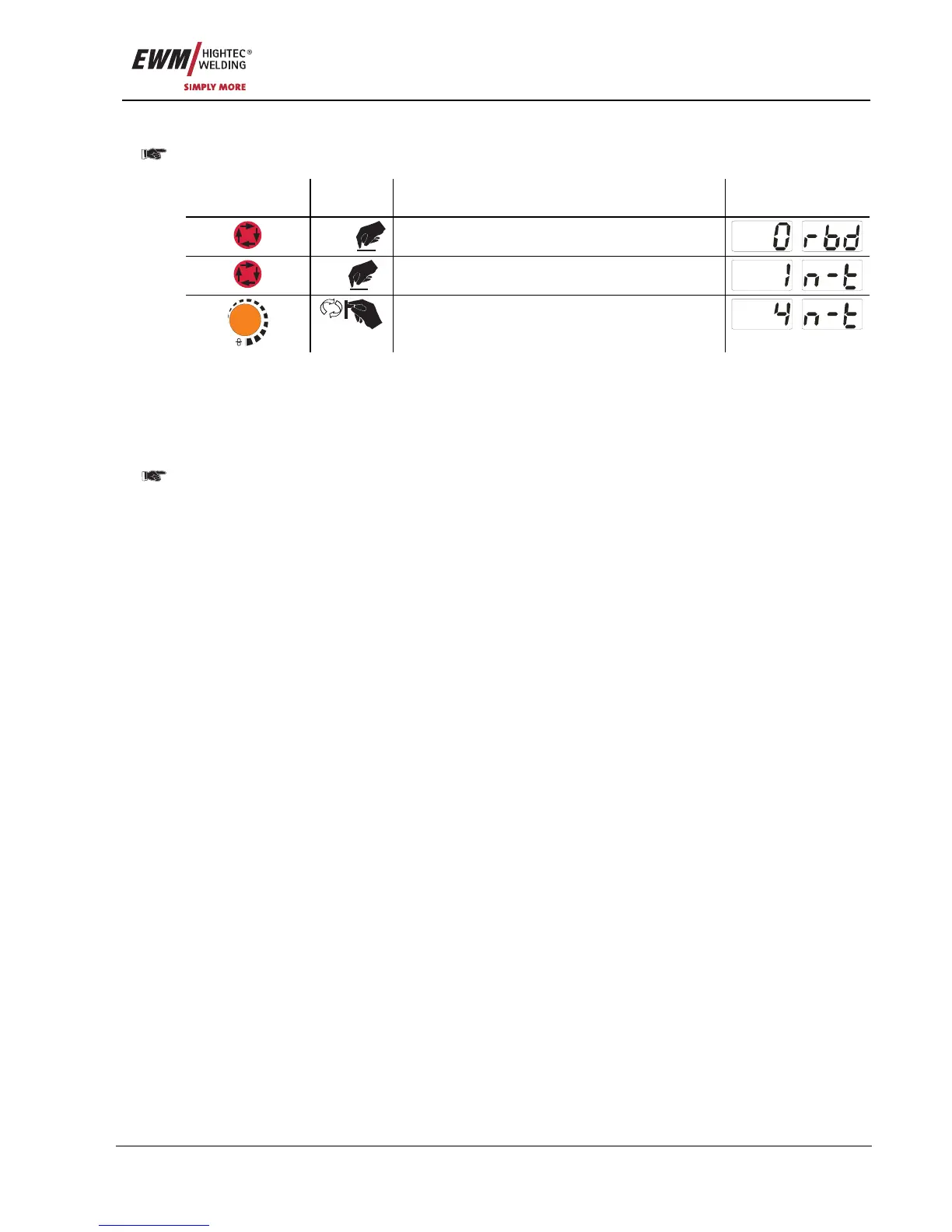
5.10.1.12 N cycle setting
In general, "Program switching with standard torch" must be set to "2" (= special latched special)
before setting the N cycle (see chapter Machine control M3.70/M3.71 – special parameters).
Operating
element
Action Result Display
3 sec
Select wire burn-back
1 x
Select N cycle setting
m/min
Parameter setting (setting range 1 to 9)
5.10.1.13 Latched/special-latched tap start (P9)
In latched – tap start – operating mode it is possible to switch straight to the second step by tapping the
torch trigger; it is not necessary for current to be flowing.
The welding can be halted by pressing the torch trigger for a second time.
5.10.1.14 "Single or dual operation" (P10) setting
In single operation, only one wire feed unit can be connected (P10 = 0)!
In dual operation, both wire feed units must be connected and configured differently on both wire
feed controllers for this operating mode!
Configuration for this welding system in dual operation:
• The first wire feed unit must be set to P10 = 1 and is identified as the master in the welding system.
• The second wire feed unit must be set to P10 = 2 and is identified as the slave in the welding system.
If one of the wire feed units is equipped with a key switch, the unit must be configured as the
master (P10 = 1). The key switch is required to protect against unauthorised use and blocks
access to most process settings (see chapter Key switch). The correction operation is also
activated.
5.10.1.15 Latched special tapping tim
e setting (P11)
The tapping time for changing over between the main program and reduced main program can be set in
three levels.
0 = no tapping
1 = 300ms (factory setting)
2 = 600ms
5.10.1.16 Software key switch (SCH)
The key
swit
ch function allows the welding machine to be locked using the software. This is useful on
units that do not have a key switch (e.g. PHOENIX 401 BASIC).