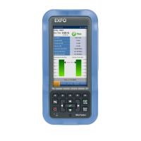
Graphical User Interface Overview
20 MAX-800 Series
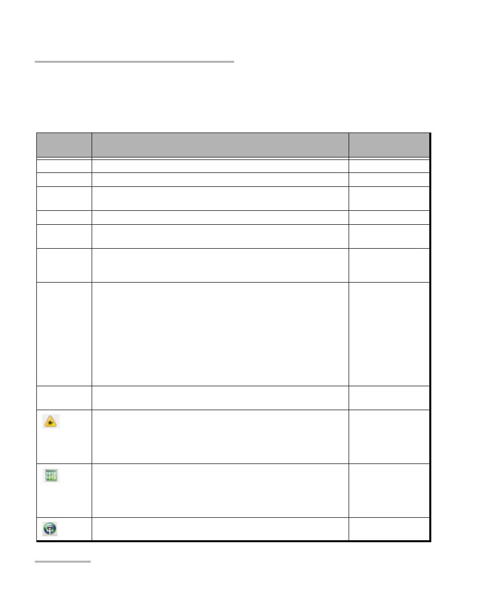
Status Bar
Status Bar
The status bar displays the following information.
Icon
and/or text
Description Test Application
Test icon Icon representing the active test application. All
P1, P2 Port identification number: Port x All
A1, A2, B1,
B2
Port identification number composed of the port type of the
MAX-890/890Q (A or B) and the transceiver port (1 or 2)
All
TX/RX, TX, RX Indicates the direction of the signal per port. Transport
Interface/
Signal
The interface or signal rate per port: 1GE Optical, OTU1, OTU2, etc. All
LINK Green arrow: Link up.
Red arrow: Link down.
Gray arrow: Awaiting incoming data to provide a status.
Transport
Ethernet
Power level The received signal level per port in dBdsx for DSn signal or dBm for
PDH and optical signals. For Transport electrical interface, LOS on red
background indicates that there is no electrical signal power. For
optical interface, the following background color are used as power
level qualifier:
Green: Power level in range.
Yellow: Power level out-of-range.
Red with “LOS”: Loss of signal.
Red with “Power”: Power level is close to damage.
Gray: Invalid operational range value.
All except Cable Test
Amplitude Amplitude indicates the received signal amplitude per port. Only
available with electrical interfaces.
Transport
Laser ON. The laser icon is not displayed when the laser is off. The laser
icon is only displayed for optical interfaces. The laser is ON by default
when the test is created. The laser control is not affected when turning
off the laser by generating a LOS for example. Refer to Laser Button on
page 385.
All
The status of the received signal pattern per port:
Green: Pattern is synchronized.
Red: Loss of pattern.
Gray: Test is not running (EtherBERT test) or the No Pattern Analysis
(Live) check box is selected.
Transport
EtherBERT
Connection established between two testing units in Dual Test Set
(DTS) or in Loop Up mode.
Ethernet