Test Setup - Test Configurator, Timer, and System
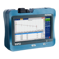
MaxTester 161
Signal
Signal
From the Test menu, tap Setup, Test Configurator, the interface block,
and the Signal tab.
Physical Interface - Optical
Note: For electrical interface, see Physical Interface - Electrical on page 163.
Optical Lane indicates the optical lane number for parallel interfaces.
Laser
1
indicates the status of the laser: ON with the laser pictogram
(emitting an optical laser signal) or OFF.
TX Power (dBm)
1
indicates, when supported, the transmit power level
of the optical lane/laser in dBm.
Wavelength (nm)
1
indicates, when supported, the detected lane/laser
wavelength.
RX Power (dBm)
1
indicates, when supported, the current received
power level of the optical lane/laser in dBm.
Green: Power level in range.
Yellow: Power level out-of-range.
Red: Loss of signal or power level is close to damage.
Gray: Invalid operational range value or not available/supplied by the
transceiver.
Min RX Power (dBm)
2
indicates, when supported, the minimum
received power level of the optical lane/laser in dBm.
Optical Interface Optical Lane Number
OTU4 (4 Lanes) [111.81 Gbit/s] 0 through 3
1. Displayed for each optical lane for parallel interfaces.
2. Displayed for each optical lane for parallel interfaces.