IN1806 and IN1808 Series Scaling Presentation Switchers • Installation 12
Installation
This section contains information on how to connect cables to the IN1806 and IN1808
Series models. Topics in this section include:
• Installation Overview
• Rear Panel Connections
• Connection Details
Installation Overview
1. Turn off or disconnect all related equipment. Ensure that video sources and output
displays are all turned off and disconnected from the power source.
2. Mount the scaler (see Mounting on page 111).
3. Connect video and audio input sources (see Rear Panel Connections).
4. Connect video and audio output devices (see Rear Panel Connections).
5. Connect desired control devices (see Rear Panel Connections).
6. Connect a power source to the scaler (see AC power connector on page 14).
7. Configure the scaler using by any of the following methods:
• Front panel menus (see Operation beginning on page 23)
• PCS (see Configuration Software beginning on page 93 to download the
software, and see the IN1806 and IN1808 Series PCS Help File to configure the
system)
• SIS commands (see SIS Configuration and Control, beginning on page 51)
Rear Panel Connections
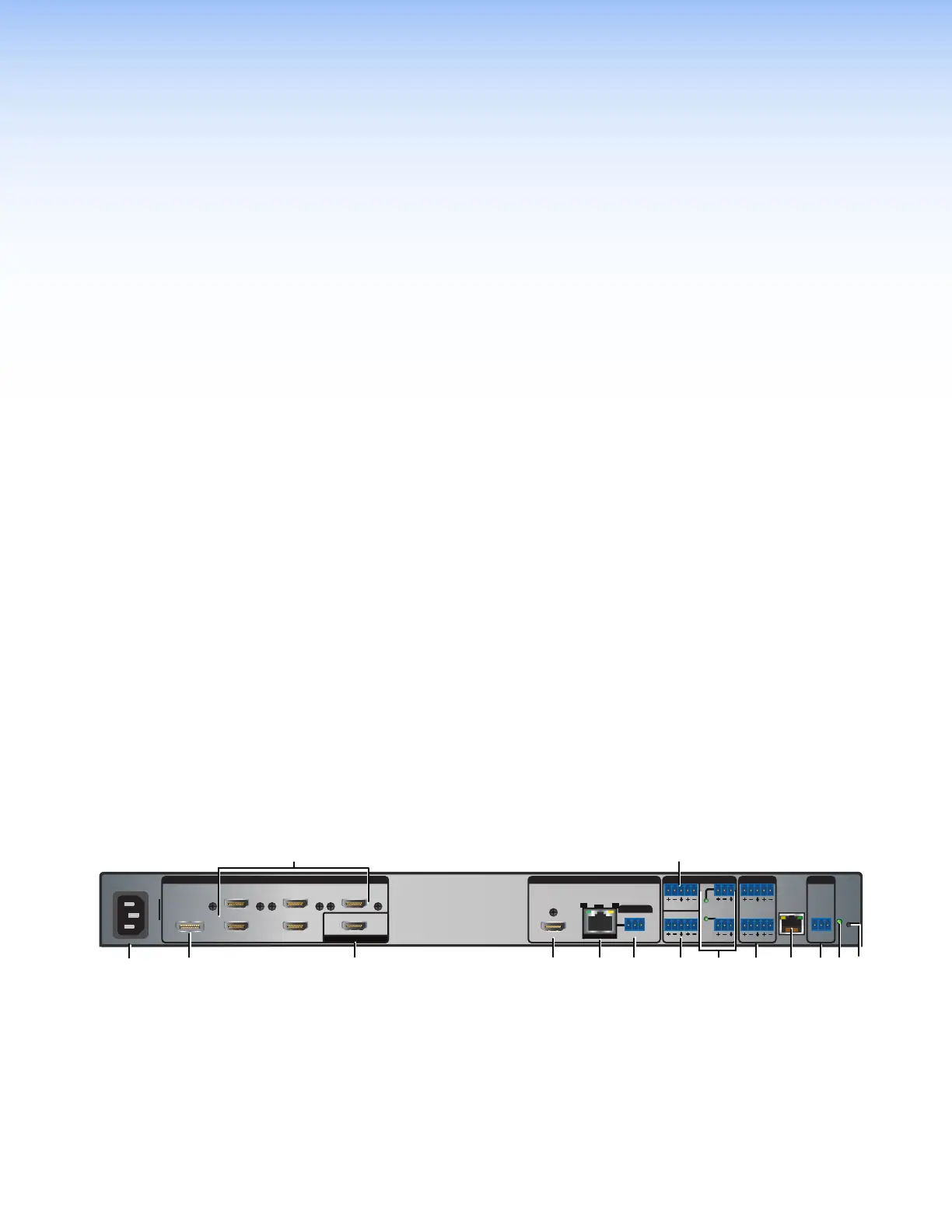
Figures 3 through 6 show the rear panels of the IN1806 and the three IN1808 Series models
(see the legend on the next page).
100-240V~0.7A MAX
31
2
5
4 6
HDMI/CEC
INPUTS AUDIO INPUTS OUTPUTS REMOTE
OVER TP
IN1806
1A 1B
SIG LINK
OUT
Tx Rx
RS-232
GTx Rx
IR
G
RESET
12
34
+48V
+48V
1
2
MIC/LINE
LR
AUX
34
LAN
LOOP OUT
P
R
OUTPUTS (DTP2/XTP/HDBT)
50-60 Hz
Figure 3. IN1806 Rear Panel
3