IN1806 and IN1808 Series Scaling Presentation Switchers • Operation 49
Changing the starting point
By default the UART start point is 2000. You can change the starting port number by any of
the following methods:
• Using the Product Configuration Software (see IN1806 and IN1808 Series PCS Help file)
• Using SIS commands (see the Set UART start point SIS command on page 80)
RS-232 protocol
You also may need to set the RS-232 protocol of the addressed port to match the connected
device. You can do this using any of the following methods:
• Using PCS (see the IN1806 and IN1808 Series PCS Help file).
• Using SIS commands (see the Serial Port Configuration SIS commands on
page 80).
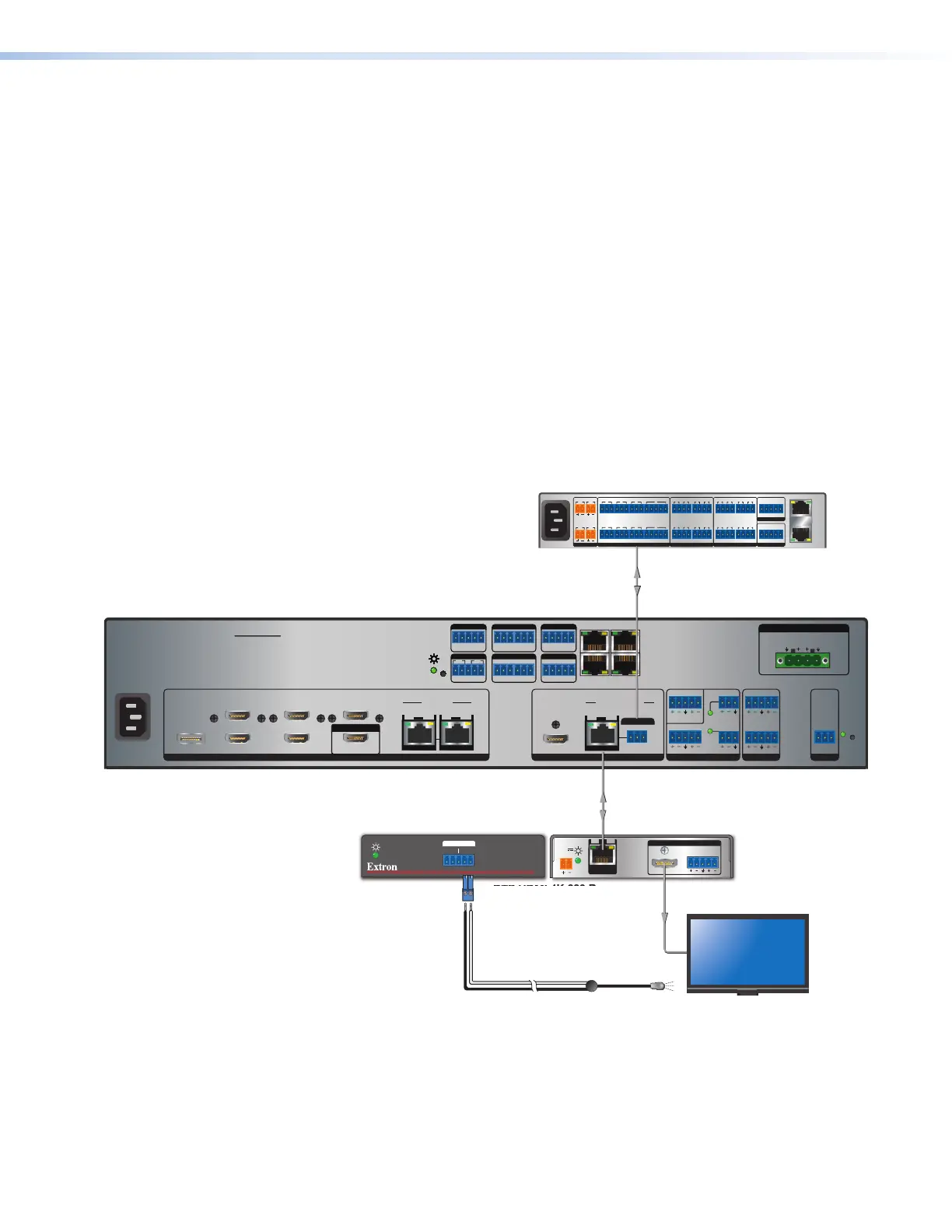
Captive Screw IR Signal Insertion
Figure 31 shows an example of a typical captive screw Ethernet insertion, in which an
Extron control system provides IR control of a display via the scaler. Configure this type of
insertion as follows:
IN1808 IPCP SA
INPUTS
LOOP OUT
31
2
5
4 6
7
SIG LINK
IN
8
DTP2/XTP
SIG LINK
IN
OUTPUTS AUDIO INPUTS OUTPUTS REMOTE
HDMI/CEC
OVER TP
1A 1B
SIG LINK
OUT
DTP2/XTP/HDBT
Tx Rx
IR
G
LAN
AV LAN 2
AV LAN 3
AV LAN 1
2x25W(8Ω)/2x50W(4Ω)
LR
CLASS 2 WIRING
AMPLIFIED OUTPUT
Tx Rx
RTSCTS
G
Tx Rx GTx Rx G
R
1234G
DIGITAL I/OCOM 3COM 2COM 1
SSGG
1
1
2
2
C34C
+S G-S+V
PWROUT = 6W
RRRRRRRRRR
R
R
R
R
R
R
R
R
R
R
R
R
R
IR/SERIAL eBUSRELAYS
Tx Rx
RS-232
G
RESET
12
34
+48V
+48V
1
2
MIC/LINE
LR
AUX
34
DTP HDMI 4K 230 Rx
DTP HDMI 230 Rx
OVER DTP
RS-232
IR
Tx Rx Tx RxG
LR
POWER
12V
0.7A MAX
AUDIO
SIG LINK
DTP IN
OUTPUTS
HDMI
1808 IPCP SA
IR
1.2A MAX
100-240V ~ 50-60Hz
PWR OUT = 12W
+V +S -S G
1
4
2 3 7
5 6 8
SGSG SGSGTx Rx GTx Rx GTx Rx GTx Rx G
RTSCTS
1 2
1 2 3 41 2 3 4
3214G
Tx Rx GTx Rx GTx Rx GTx Rx G
RTS
CTS
SGSG SGSG
5 6 7 8 5 6 7 8
SWITCHED 12 VDC
40W MAX TOTAL
3 4
COM
eBUS
FLEX I/ORELAYSIR/SERIAL
12 VDC
AV
LAN
LAN
Control
Processor
IR
Front Panel
Rear Panel
IR Emitter
50-60 Hz
100-240V~1.5A MAX
Figure 31. Typical Captive Screw Insertion to an Input Endpoint
31