IN1806 and IN1808 Series Scaling Presentation Switchers • Operation 48
Ethernet to RS-232 Insertion
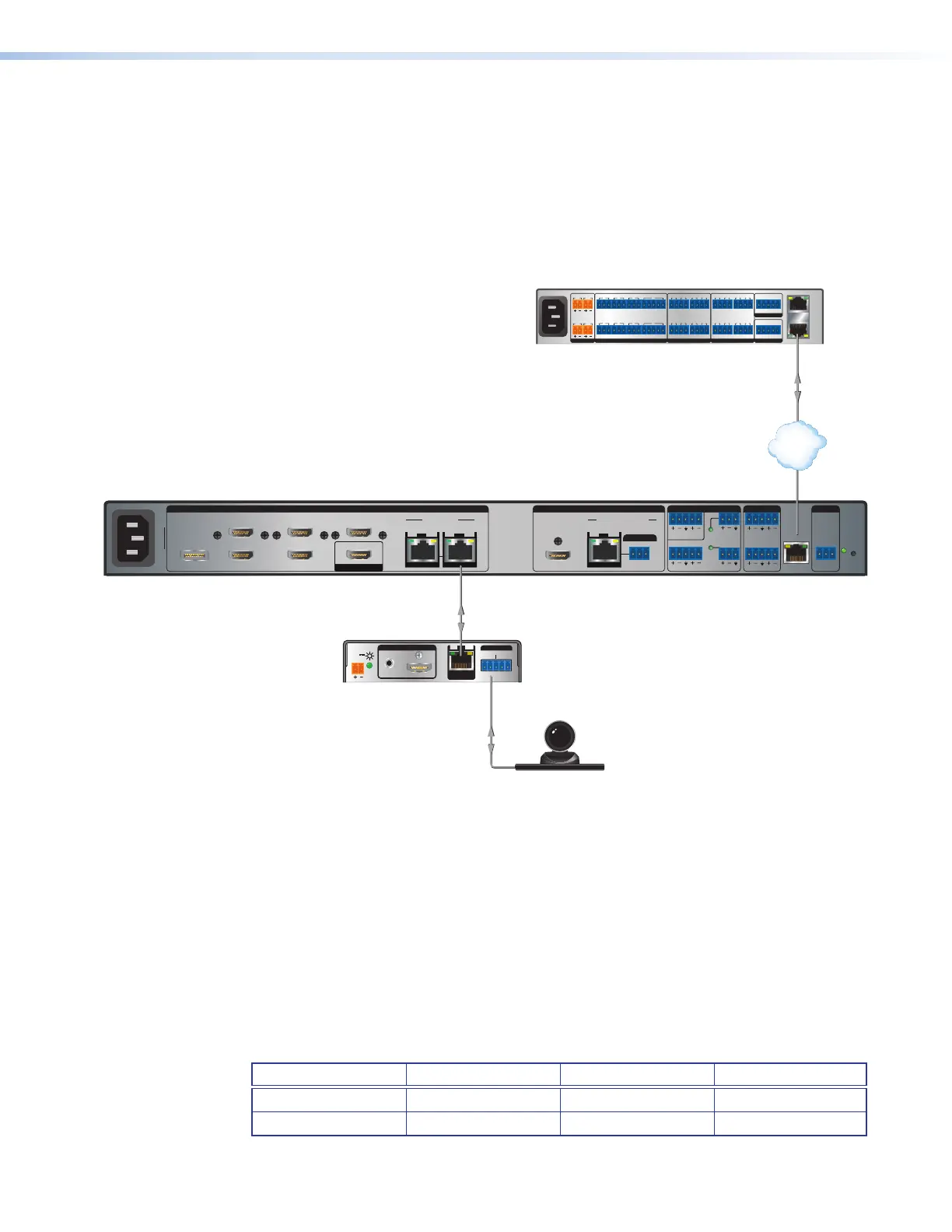
Figure 30 is an example of an Ethernet to RS-232 insertion, in which an Extron
controller provides control of an HD camera via the IN1806 and IN1808 Series and a
DTP HDMI 4K 230 transmitter. Configure this type of insertion as follows:
1. Connect a TP cable from the control system to the scaler LAN port, directly or via a
network.
2. If necessary to match the device to be controlled, configure the port RS-232 protocol
(baud rate, parity, data bits, and stop bits) (see RS-232 protocol on the next page).
AUDIO
INPUTS OVER DTP
RS-232
IR
Tx Rx Tx RxG
POWER
12V
0.7A MAX
SIG LINK
DTP OUT
DTP HDMI 4K 230 Tx
100-240V 50/60 Hz
--A MAX
31
2
5
4 6
HDMI/CEC
INPUTS OUTPUTS AUDIO INPUTS OUTPUTS REMOTE
OVER TP
IN1808
7
SIG LINK
IN
81A
DTP2/XTP II
SIG LINK
IN
1B
SIG LINK
OUT
DTP2/XTP/HDBT
LOOP OUT
Tx Rx
RS-232
GTx Rx
IR
G
RESET
12
34
+48V
+48V
1
2
MIC/LINE
LR
AUX
34
LAN
31
2
5
4 6
HDMI/CEC
INPUTS OUTPUTS AUDIO INPUTS OUTPUTS REMOTE
OVER TP
IN1808
7
SIG LINK
IN
81A
DTP2/XTP
SIG LINK
IN
1B
SIG LINK
OUT
DTP2/XTP/HDBT
LOOP OUT
Tx Rx
RS-232
GTx Rx
IR
G
RESET
12
34
+48V
+48V
1
2
MIC/LINE
LR
AUX
34
LAN
RS-232
RS-232
1808 (base model)
1.2A MAX
100-240V ~ 50-60Hz
PWR OUT = 12W
+V +S -S G
1
4
2 3 7
5 6 8
SGSG SGSGTx Rx GTxRxG TxRx GTxRxG
RTSCTS
1 2
1 2 3 41 2 3 4
3214G
Tx Rx GTxRxG TxRx GTxRxG
RTS
CTS
SGSG SGSG
5 6 7 8 5 6 7 8
SWITCHED 12 VDC
40W MAX TOTAL
3 4
COM
eBUS
FLEX I/ORELAYSIR/SERIAL
12 VDC
AV
LAN
LAN
IPCP Pro 555
Control
Processor
RS-232 Insertion
Network
100-240V 50/60 Hz
50-60 Hz
100-240V ~ 1.5A MAX
Figure 30. Typical Ethernet to RS-232 Insertion to an Input Endpoint
3. Connect the TP cable to the endpoint as usual.
4. Connect a serial cable from the endpoint to the device to be controlled.
Port number
For Ethernet to RS-232 insertion, the insertion port number must be stated from a specific
universal asynchronous receiver-transmitter (UART) start point. This number is entered as
the Telnet port number when you establish communication with the insertion port.
For the purposes of this discussion, consider the Ethernet insertion ports as serial (RS-232)
ports. The input insertion port number is the UART start point + 1. The output insertion port
number is the UART start point +3. With the default UART start point of 2000, the input and
output insertion ports are:
Input Ports Insertion Port Output Port Insertion Port
7 2001 1B 2003
8 2002
30