IN1806 and IN1808 Series Scaling Presentation Switchers • Installation 19
5
LAN port — Single Ethernet connector. The IN1806 and the IN1808 base model
each have a LAN connector to the left of the Remote RS-232 connector (see
figures 3 and 4,
K
, on pages 12 and 13) instead of the LAN and AV LAN ports on
the IPCP models (see figures 5 and 6,
Q
, on page 13).
6
eBUS port — 5-pole captive screw connector supporting up to eight eBUS
endpoints, with a maximum power output of 9 watts
7
Relay ports — Four relays on two 3-pole captive screw connectors containing
individual contacts for each relay and a shared Common (C) connector. Each relay
supports 24 VDC of power and up to 1 amp of current.
8
IR/Serial ports — Two unidirectional RS-232 or IR ports (configurable), which
share a single 5-pole captive screw connector
9
Reset button and LED — Pressing this recessed button causes various IPCP
settings to be reset to the factory defaults. The green power LED blinks depending
on the selected reset mode.
R
HDMI input connectors (Inputs 2 through 6) — Connect HDMI video sources to
these female HDMI connectors.
TIP: Use Extron HDMI LockIt Lacing Brackets to secure HDMI cables to the device
(see HDMI Connections on page 20).
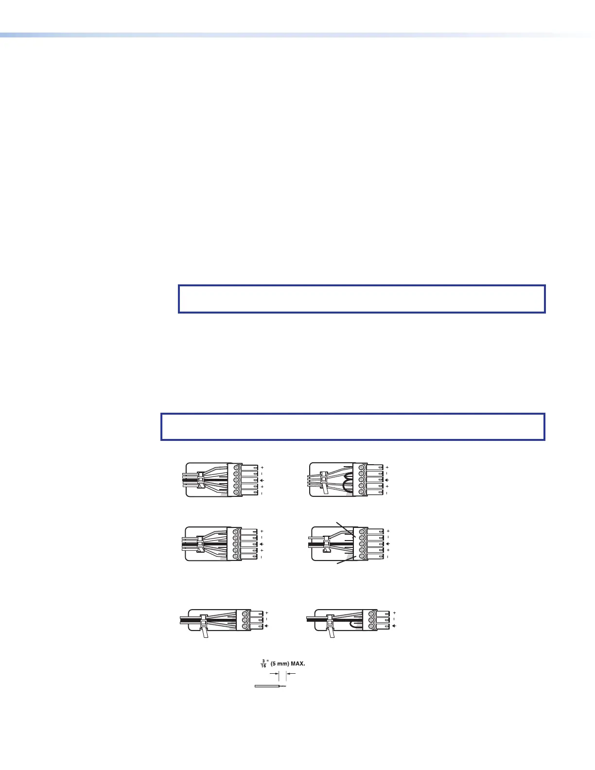
Connection Details
Analog Audio Connections
Wire the audio input and output connectors as shown in figure 10. Use the supplied tie
wrap to strap the audio cable to the extended tail of the connector.
NOTE: These instructions do not apply to the amplified audio output connector on the
IN1808 IPCP SA and MA models.
Balanced Audio Output
Tip
Ring
Tip
Ring
Sleeves
Unbalanced Audio Output
Tip
No Ground Here
No Ground Here
Tip
Sleeves
LR
Unbalanced Audio InputBalanced Audio Input
Tip
Ring
Tip
Ring
Sleeves
Tip
Sleeve
Sleeve
Tip
LR
LR
Do not tin the wires!
Audio Inputs and Outputs 1 – 4 and Aux
Mic/Line Inputs 1 and
2
Balanced Audio Input
Tip
Sleeve
Ring
Unbalanced Audio Input
Tip
Sleeve
Figure 10. Analog Audio Wiring
10