IN1806 and IN1808 Series Scaling Presentation Switchers • Operation 47
RS-232 and IR Signal Insertion
The twisted pair input and output ports allow you to insert RS-232 and IR control signals
onto the same cable that carries video and audio to extend them to the Over TP port on
a connected endpoint (see figure 30 on the next page and figure 31 on page 49). The
control signals can be inserted two ways:
RS-232 communication can be sent to the far end of the twisted pair connection via a
LAN or an AV LAN (IPCP models only) connector. A control signal applied to an IN1806 or
IN1808 Series LAN port can be routed to the RS-232 port of any connected twisted pair
device (see Ethernet to RS-232 Insertion on the next page).
When connected to an Ethernet LAN, the scaler can be accessed from a computer running
a standard Internet browser. Use a patch or crossover cable to connect the IN1806 or
IN1808 Series device to a computer, control device, router, or switch.
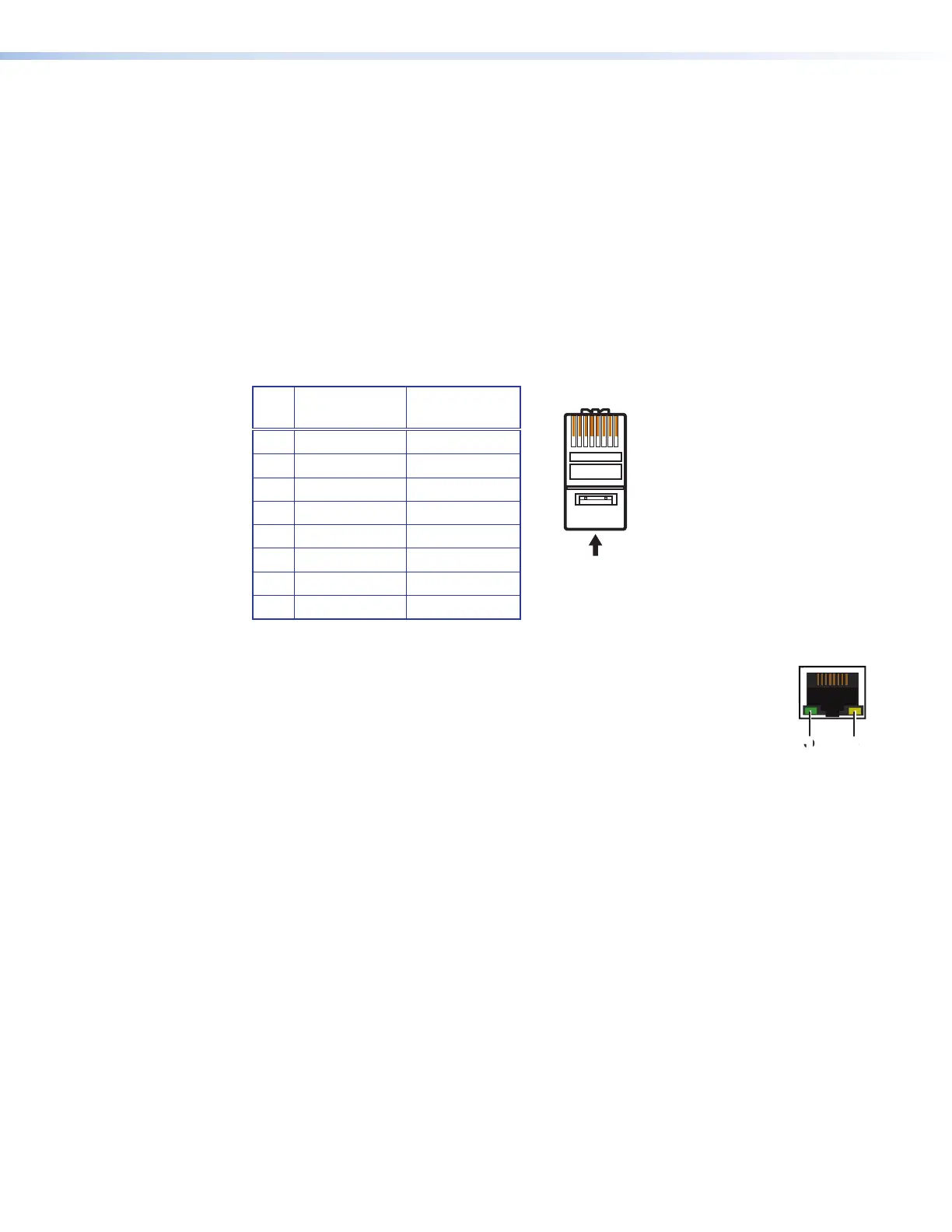
Pin T568A
Wire Color
T568B
Wire Color
1 White-green White-orange
2 Green Orange
3 White-orange White-green
4 Blue Blue
5 White-blue White-blue
6 Orange Green
7 White-brown White-brown
8 Brown Brown
Figure 29. Connecting to the LAN Port
The LAN and AV LAN connectors contain two LEDs (see the illustration at right):
1
Link LED — This green LED lights steadily to indicate a LAN connection.
2
Act LED — This amber LED blinks to indicate LAN signal activity.
The default IP address of the scaler is 192.168.254.254, the default subnet
mask is 255.255.255.0, and the default gateway address is 0.0.0.0.
The two methods of signal insertion are:
• Ethernet to RS-232 insertion (see “Ethernet to RS-232 Insertion”) — A control signal
applied to the IN1806 and IN1808 Series LAN port can be routed to the RS-232 port of
any connected twisted pair device. The RS-232 insert inputs and outputs inserted via
Ethernet can support up to a 115K baud rate.
• Captive screw IR insertion (see Captive Screw IR Signal Insertion on page 49) —
(IR only) A control signal applied to the IR Over TP captive screw port is tied directly to
TP Output 1B.
You must physically connect a cable to the captive screw connector where a control
signal is to be inserted.
29
12345678
RJ-45
t T
Pair Wires
LAN
11
22