4-26
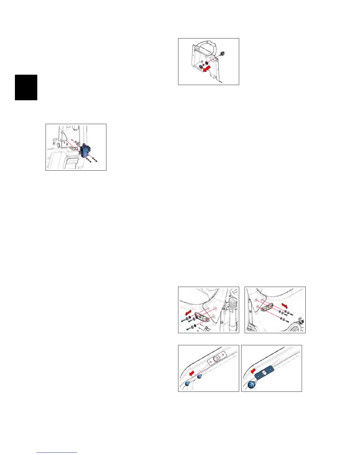
• Loose the screws that block the
Brush Motor Contactor to the Elec-
tric Panel (see fig. 4.1.11-19).
• Remove the Brush Motor Contac-
tor(see fig. 4.1.12-20).
• Proceed at reverse to refit the part.
4.1.12-20
4.1.13 Brush Release Switch
IMx BB
• Put the machine in safe conditions.
• Remove the Function Dashboard (see
section 4.1.2 at page 17)
• Remove the Rear Dashboard (see section
4.1.6 at page 18)
• Loose the Rubber Cap that protect
the Brush Release Switch (Rif. SBR)
(see fig. ??).
• Loose the nut that blocks the Brush
Release Switch to the Rear Dash-
board (see fig. 4.1.13-21).
• Remove the Brush Release Switch
from the Rear Dashboard.
• Proceed at reverse to refit the part.
4.1.13-21
4.1.14 Dead Man Switch
• Put the machine in safe conditions.
• Loose the screws and remove the
handle (see fig. 4.1.14-22) (see fig. 4.1.14-23).
• Unplug the bipolar connector that
connects the Dead Man Switch to
the Electrical installation of the ma-
chine (it’s on the right hand side of
the handle).
• Remove the screws that secure the
microswitch support to the handle-
bar (see fig. 4.1.14-24) (see fig. 4.1.14-25).
• Remove the Dead Man Switch.
• Proceed at reverse to refit the part.
4.1.14-22 4.1.14-23
4.1.14-24 4.1.14-25