4-40
4.5 Solution Delivery Sys-
tem
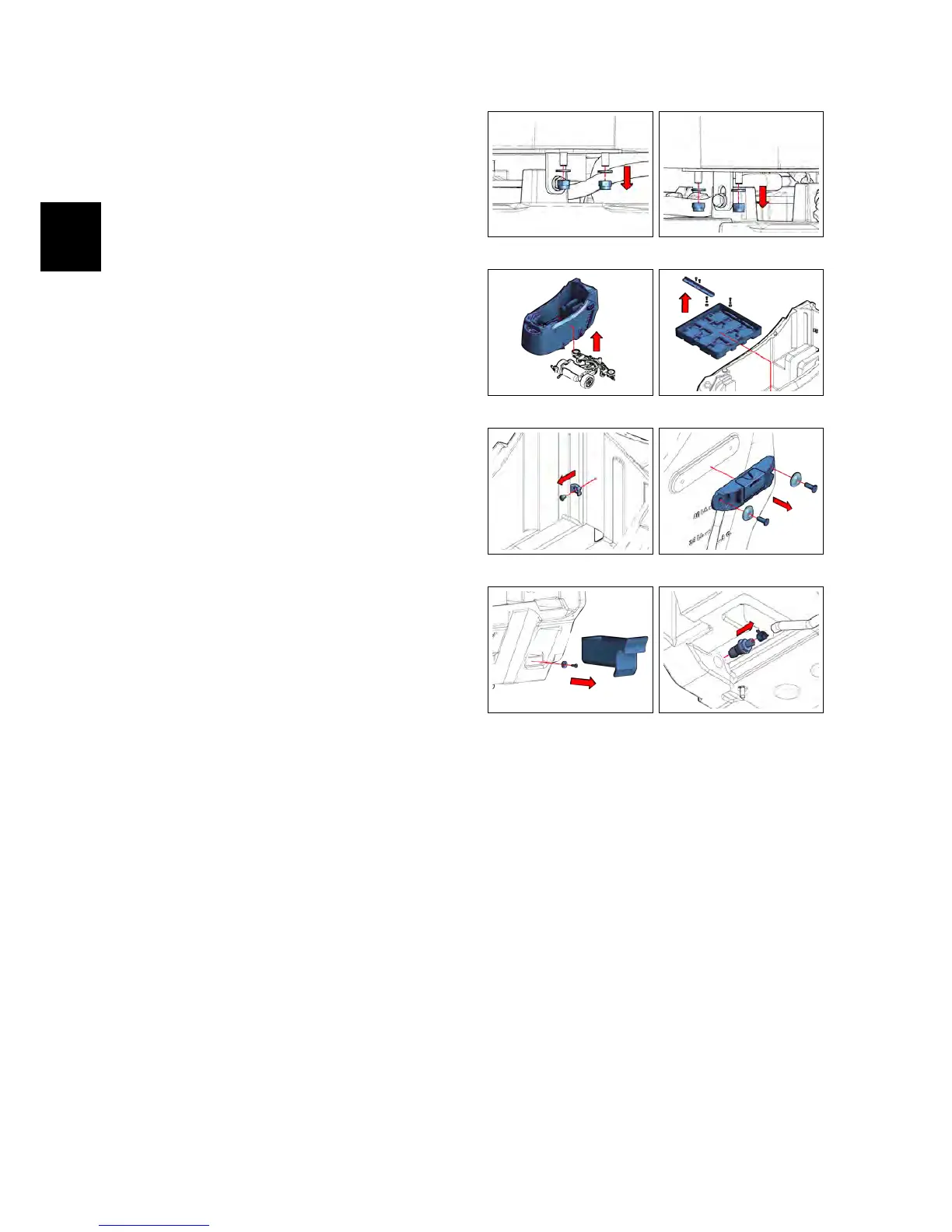
4.5.1 Solution Tank
• Put the machine in safe conditions.
• Remove the recovery tank. (see section
4.3.7 at page 28)
• Disconnect the water supply hose
from the solenoid valve.
• Loosen the screws securing the so-
lution tank to the scrubdeck (see fig.
4.5.1-88) (see fig. 4.5.1-89) .
• Remove the solution tank from the
machine frame (see fig. 4.5.1-90).
• Loosen the screws of the battery
compartment and remove it from the
tank (see fig. 4.5.1-91).
• Remove the Support plate unscrew-
ing the fixing screws. (see fig. 4.5.1-92)
• Remove the brush/squeegee holder,
by unscrewing the fixing screws (see
fig. 4.5.1-93)
• Remove the object holder and un-
screw the screw on the magnet. (see
fig. 4.5.1-94)
• Remove the solution filter (see section
4.5.3 at page 36)
• Remove the water control Valve
Group (see section 4.5.4 at page 36).
• Remove the hose connector and its
fastening clamp (see fig. 4.5.1-95)
• Remove the parking brake (ONLY BT
VERSION) (see section 4.4.6 at page 34)
• Remove the vacuum motor (see section
4.3.10 at page 29)
• Remove the vacuum motor lower
carter.
• Proceed at reverse to refit the part.
4.5.1-88 4.5.1-89
4.5.1-90 4.5.1-91
4.5.1-92 4.5.1-93
4.5.1-94 4.5.1-95