4-29
4.2.3 Brush Coupling Flange
• Put the machine in safe conditions.
• Disassemble the Brush Deck from
the machine (see section 4.2.2 at page 23).
• Put the Brush Deck to let the Motor
Head touch the floor (or a table).
• Unscrew the Coupling Flange rotat-
ing it in the same direction as the
brush in standard working condi-
tions (see fig. 4.2.3-36).
• Remove the spacer (see fig. 4.2.5-40).
• Proceed at reverse to refit the part.
Note: Before to refit the part lubricate
the thread in order to prevent blockings
because of dirt or oxide.
4.2.3-36 4.2.3-37
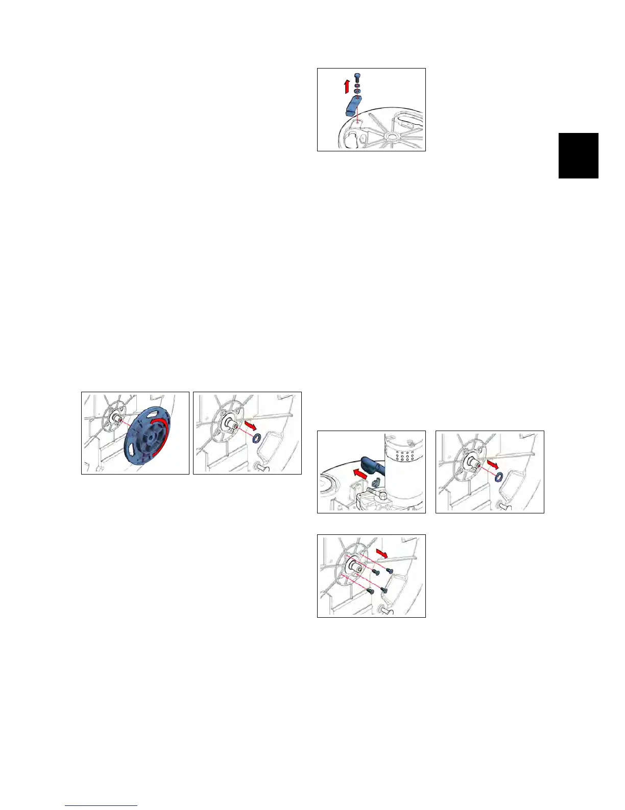
4.2.4 Brush Stopper Spring
• Put the machine in safe conditions.
• Disassemble the Brush Coupling
Flange (see section 4.2.4 at page 24).
• Loose the screw that block the
Brush Stopper Spring.
• Remove the Brush Stopper Spring
(see fig. 4.2.4-38).
• Proceed at reverse to refit the part.
4.2.4-38
4.2.5 Brush Motor
• Put the machine in safe conditions.
• Disassemble the Brush Coupling
Flange (see section 4.2.4 at page 24).
• Unplug the Solution Hose that con-
nects the Solenoid Valve to the
Brush Motor (see fig. 4.2.5-39).
• Loose the 4 blocking screws and re-
move the Brush Motor (see fig. 4.2.5-41).
• Proceed at reverse to refit the part.
Note: Use the thread lock liquid on the
screw during the assembling.
4.2.5-39 4.2.5-40
4.2.5-41