4-37
4.4 Frame and Traction
System
4.4.1 Wheels
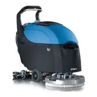
• Put the machine in safe conditions.
• Lift up the wheel from the ground.
• Loose the screw that blocks the
wheel to the Drive Shaft (see fig. 4.4.1-
77).
• Remove the wheel pulling it by
hands or using a extractor.
• Proceed at reverse to refit the part
(Use the thread lock liquid on the
screw during the assembling).
4.4.1-77
4.4.2 Drive Shaft IMx BT
• Put the machine in safe conditions.
• Disassemble the wheel connected to
the axle in question (see section ?? at page
??).
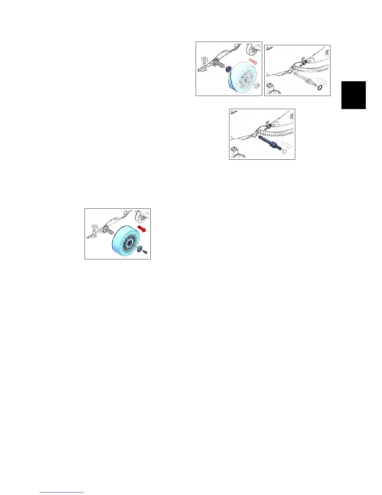
• Remove the spacer (see fig. 4.4.2-78).
• Remove the seeger (see fig. 4.4.2-79).
• Remove the Drive Shaft from the
traction motor pulling it by hands or
using an extractor (see fig. 4.4.2-80).
• Remove the bearings from the Drive
Shaft using an extractor (see fig. 4.4.2-
80).
• Proceed at reverse to refit the part.
4.4.2-78 4.4.2-79
4.4.2-80
4.4.3 Traction Gearmotor IMx
BT
• Put the machine in safe conditions.
• Disassemble both wheels (see section ??
at page ??).
• Disassemble both Drive Shafts from
the Machine (see section ?? at page ??).
• Unplug the Electrical connector of
the Traction Gearmotor (see fig. 4.4.3-81).
• Loose the screws that block the
Traction Gearmotor to the Machine
Frame (see fig. 4.4.3-82).
• Remove the Traction Gearmotor (see
fig. 4.4.3-83).
• Remove the Spacer from the Trac-
tion Gearmotor (see fig. 4.4.3-83).
• Proceed at reverse to refit the part.
4.4.4 Free Shaft IMx B-BB
• Put the machine in safe conditions.
• Disassemble both wheels (see section ??
at page ??).
• Disassemble the seeger (see fig. 4.4.4-84)