10-92
Installing instructions
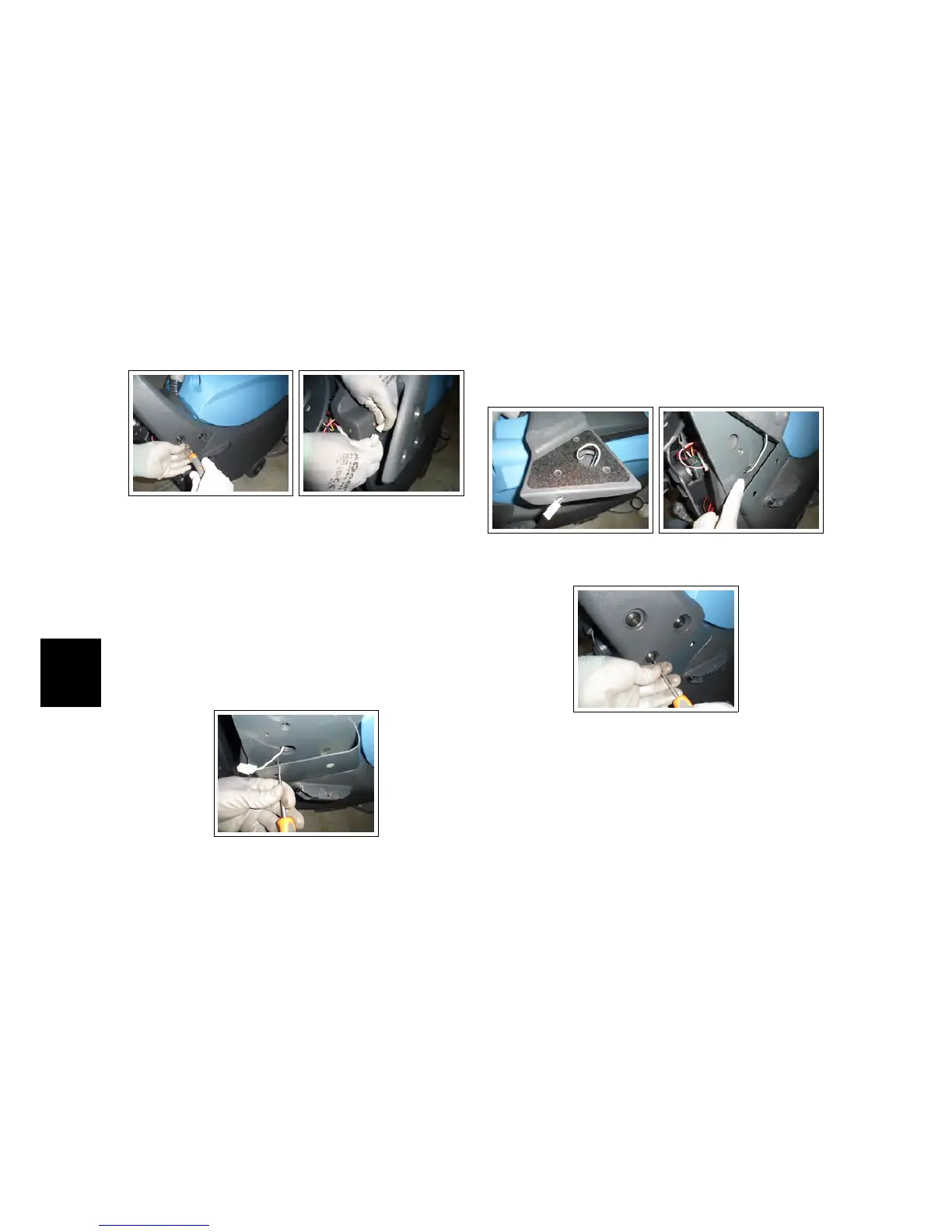
• Remove the handle from the ma-
chine by unscrewing the screws on
both sides. (see fig. 10.4.3-26)
• Disconnect the connector of the
handlebar microswitch from the
electrical system (Being careful to
keep the connector outside of the
electrical system compartment) (see fig.
10.4.3-27).
10.4.3-26 Handlebar re-
moving
10.4.3-27 Connector
• Remove the Function Dashboard (see
section 4.1.2 at page 17)
• Remove the Rear Dashboard (see section
4.1.6 at page 18)
10.4.3-28 Extensions in-
stallation
• Fit the two extensions to the solu-
tion tank with the two screws 5x12
passing in the two respective lower
holes. (Pull the connector through
the lower large hole of the exten-
sion)(see fig. 10.4.3-28).
• On the handlebar, enlarge the hole
under in the connector’s side, bring-
ing it to 14 diameter.
• Pass the connector through the en-
larged hole (see fig. 10.4.3-29).
• Reconnect the connector of the han-
dlebar microswitch to the electrical
system.
• Pulling gently, accompany the con-
nector inside the electrical system
compartment (see fig. 10.4.3-30).
• Install the handle to the supports
with the screws included in the kit
(see fig. 10.4.3-31).
10.4.3-29 Enlarged hole 10.4.3-30 Connector
pulling
10.4.3-31 Handlebar in-
stallation
• Restore the Rear Dashboard.
• Restore the Function Dashboard.