Home
Flintec
Control Unit
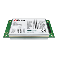
EM100-C
Flintec EM100-C - User Manual
81 pages
Manual
Specs
Ask a question
Save Page as PDF
To Next Page
To Next Page
Loading...
EM100-
C User Manual
0084292
Page
1
of
81
User Man
ual
EM100-C
v
1.
5
February
2020
2
Table of Contents
Main Page
Table of Contents
2
EM100 Module
7
Introduction
7
Disclaimer
8
Safety Instructions
9
Specification
10
Getting Started
11
Labelling
11
Dimensions
12
Connections
13
Load-Cell Connections
14
Power Connection
15
RS-232 Connection
16
RS-485 Connection
17
Canopen Connection
18
USB Connection
18
EM100 with Adaptor Board
19
Driver Check
20
Calibration
21
Calibration Commands
21
Preparing for Calibration
21
Calibration Sequence
22
Commands Overview
23
Command Descriptions
26
System Diagnostic Commands -FPN, FFV, IS, SR, RS
26
FPN Get Device Identity
26
FFV Get Firmware Version
26
IS Get Device Status
26
SR Software Reset
27
RS Read Serial Number
27
Calibration Commands - CE, CM'n', CI, MR, DS, DP, CZ, CG, ZT, FD, IZ, ZR, ZI, TM
28
Tn, Zn, Az, Ag, Wt
28
CE Read TAC Counter/Open Calibration Sequence
28
CM 'N' Set Maximum Output Value
28
CI Set Minimum Output Value
29
MR Set Multi-Range/Multi-Interval
29
DS Set Display Step Size
29
DP Set Decimal Point Position
30
Set Calibration Zero Point
30
CG Set Calibration Gain (Span)
30
ZT Enable/Disable Zero-Tracking
31
FD Reset to Factory Default Settings
31
IZ Correction of System Zero
31
ZR Zero Range
32
ZI Initial Zero Range
32
TM Tare Mode
32
TN Set/Clear Non-Volatile Tare
33
ZN Set/Clear Non-Volatile Zero
33
AZ Absolute Zero Point Calibration (Ecal)
33
AG Absolute Gain Calibration (Ecal)
34
WT Warm-Up Time
34
Motion Detection Commands - NR, NT
35
NR Set No-Motion Range
35
NT Set No-Motion Time
35
Filter Setting Commands - FM, FL, UR
36
FM Filter Mode
36
FL Filter Setting
36
UR Update Rate & Averaging
38
Taring & Zeroing Commands - SZ, RZ, ST, RT, SP, TMV, RMV
39
SZ Set System Zero
39
RZ Reset Zero
39
ST Set Tare
40
RT Reset Tare
40
SP Set Preset Tare
40
TMV Set Tare (MV/V)
40
RMV Reset Tare (MV/V)
41
Output Commands - GG, GN, GT, GS, GMV, GW, GA, GL, OF, GH, TH, GM, RM, GO
42
Gv, Hw
42
GG Get Gross Value
42
GN Get Net Value
42
GT Get Tare Value
42
GS Get ADC Sample Value
42
GMV Get MV/V Value
42
GW Get Data String (Net, Gross & Status)
43
GA Get Triggered Average Value
44
GL Get Data String (Average, Gross & Status)
44
OF Output Format of Data String
44
GH Get Hold Value
45
TH Trigger Hold Value
45
GM Get Peak Value
45
RM Reset Peak Value
45
GO Get Peak-To-Peak Value
45
GV Get Valley Value
46
HW Hold Weight
46
Auto-Transmit Commands - SG, SN, SX, SMV, SA, SL, SW
47
SG Send Gross Value Continuously
47
SN Send Net Value Continuously
47
SX Send ADC Sample Value Continuously
47
SMV Send MV/V Sample Value Continuously
47
SA Send Triggered Average Value Continuously
47
Send Data String Continuously (Average, Gross & Status)
48
SW Send Data String Continuously (Net, Gross & Status)
48
Commands for External I/O Control - IN, OM, IO
49
IN Read Status of Logic Inputs
49
OM Control of Logic Outputs by Host Application
49
IO Read/Modify Status of Logic Outputs
49
Set-Point Output Commands - S'n', H'n', A'n
51
S'n' Set-Point Value
51
H'n' Hysteresis & Switching Action for Set-Point
51
A'n' Source Allocation for Set-Point
52
Communication Setup Commands - AD, NA, NS, BR, DX, CL, OP, TD, CTR, STR, SBR
53
AD Device Address - Serial Channel
53
NA Network Address - Canopen
53
NS Network Settings - Canopen
53
BR Baud-Rate - Serial Channel
54
DX Full-Duplex - Serial Channel
54
CL Close Device Address 'N
54
OP Open Device
54
TD Transmission Delay
55
CTR Set CAN Bus Termination Resistance
55
STR Set RS-485 Termination Resistance
55
SBR Set RS-485 Biasing Resistance
55
Save Calibration & Setup Data Commands - CS, WP, SS
56
CS Save Calibration Data
56
WP Save Setup Parameters
56
SS Save Set-Point Parameters
56
Trigger Commands - SD, MT, TE, TR, TL
57
SD Start Delay Time
57
MT Measuring Time
57
TE Trigger Edge
57
TR Software Trigger
58
TL Trigger Level
58
Re-Trigger Commands - RW, TT, TS, DT, TW, TI, HT
59
RW Re-Trigger Window
59
TT Average Time for Re-Trigger Function
59
TS Stop Value for Re-Trigger Function
59
DT Short-Time Averaging Period
60
TW Window for Automatic Taring
60
TI Average Time for Automatic Taring
60
HT Hold-Time for All Set-Points
60
Canopen Interface
62
General Interface Specification
62
Pdos
63
TPDO Frame (TPDO1, TPDO2 & TPDO3)
65
TPDO Frame (TPDO4)
65
Receive Pdos (RPDO1 & RPDO2)
66
Sdos
67
Communication Profile
68
Object Dictionary
68
Canopen Frames
76
SDO CAN Frame
76
Overall CAN Frame
77
SDO Write
78
NMT Master Message
79
Heartbeat Message
79
Emergency Message
79
Need help?
Do you have a question about the Flintec EM100-C and is the answer not in the manual?
Ask a question
Flintec EM100-C Specifications
Print Specification
General
Power supply
100 - 240 VAC
Approval
OIML
Operating temperature
-10°C to +40°C
Display
LCD
Interface
RS232
Output
RS232
Related product manuals
Flintec EM100-F
93 pages