EM100-C User Manual
0084292
Page 51 of 81
5.9. Set-Point Output Commands – S’n’, H’n’, A’n’
Each logic output can be assigned to an independent set-point value (S’n’) with a corresponding
hysteresis/switch action (H’n’) and allocation (A’n’ – source is the Gross, Net or Average weight).
Note: All changes to the set-point commands must be stored in non-volatile memory using the ‘SS’
command.
5.9.1. S‘n’ Set-Point Value
A set-point is the trigger level that causes action of the output channel, according to the settings of
the controls A’n’ and H’n’.
Request: Set-Point S0=10000dec.
Setup: Set-Point S0=3000dec.
Request: Set-Point S1=11000dec.
Setup: Set-Point S1=5000dec.
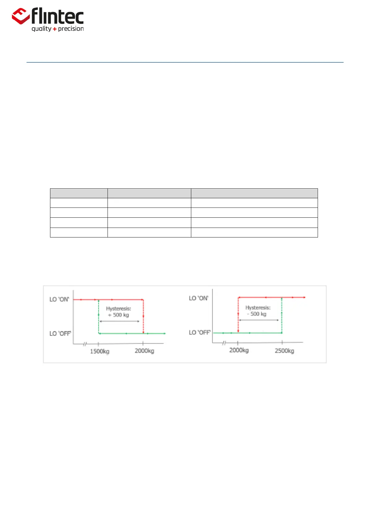
5.9.2. H’n’ Hysteresis & Switching Action for Set-Point
The set-point switching logic is defined by the numeric value and polarity of the hysteresis.
Examples of the switching actions for a Set-Point value of 2,000kg.