EM100-C User Manual
0084292
Page 30 of 81
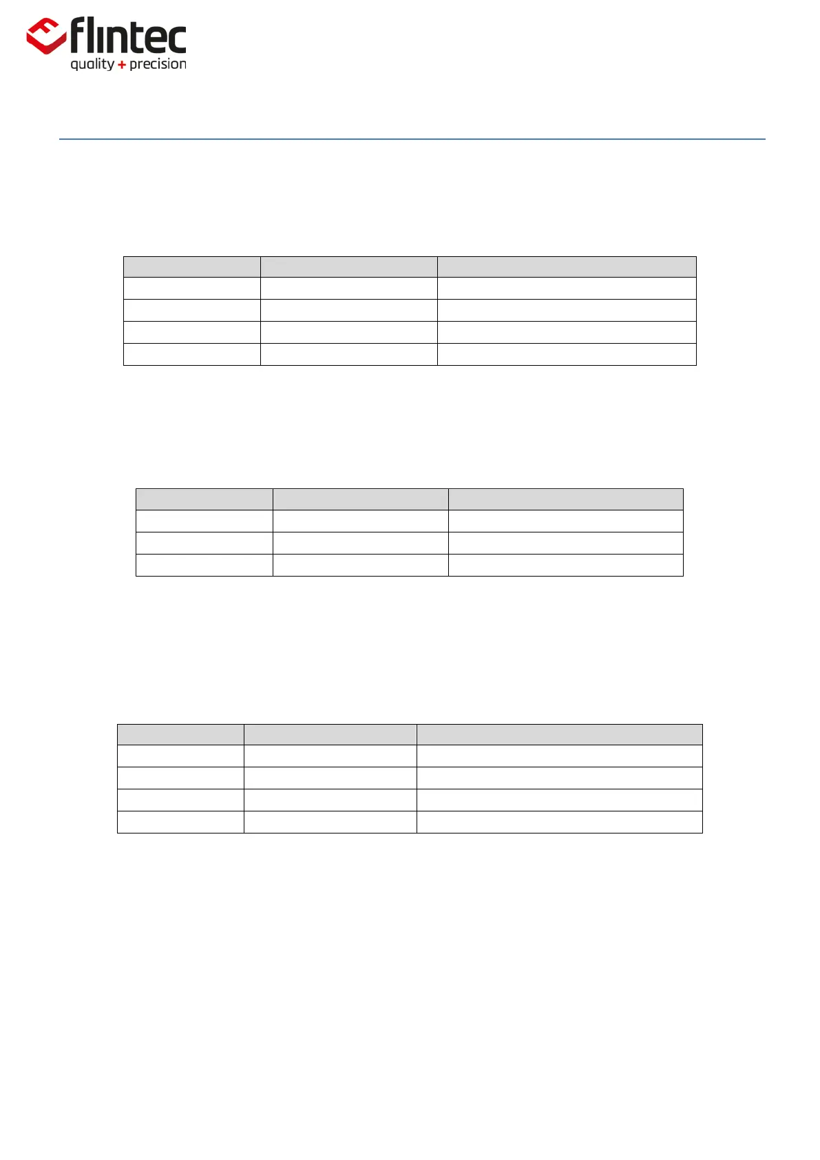
5.2.6. DP Set Decimal Point Position
This command allows the decimal point to be positioned anywhere between left-most and right-most
digits of the 5-digit output result. Permitted values are 0, 1, 2, 3, 4 and 5.
Request: Position of Decimal Point.
Request: TAC Counter CE11.
Calibration Sequence Active.
Factory default: 3.
5.2.7. CZ Set Calibration Zero Point
This is the reference point for all weight calculations and is subject to TAC control.
Request: TAC Counter CE11.
Calibration Sequence Active.
Factory Default: approx. 0mV/V input signal.
5.2.8. CG Set Calibration Gain (Span)
This is the reference point for calibration under load and is subject to TAC control.
Permitted values are from 1 to 99999.
Request: Calibration Weigh=10000dec.
Request: TAC Counter CE11.
Calibration Sequence Active.
Setup: Calibration Weight=15000dec.
For calibrating an input signal near the display maximum (‘CM’) will give the best system
performance. The minimum calibration load of at least 20% is recommended. If the calibration
weight smaller than 1% of display maximum (‘CM’), the EM100 will respond with an error message
(‘ERR’).
Factory Default: 20,000=2.000mV/V input signal.