Part 01: Prepare
1. Remove the spray shield, and then remove the nozzle nut and mixing tube from the mixing
chamber.
2. Slide the mixing tube out of the nozzle nut, and then remove the spacer and set it aside.
3. Install the mixing tube into the nozzle nut, and then install the assembly into the mixing
chamber. Make sure that the mixing tube collar is in the correct position.
4. Home the Z, A, B axis, and then jog the Y-axis until it is approximately 457 mm (18 in.) from
the front of the table. Ensure that you can reach the cutting head with the magnetic base and
dial indicator.
5. In FlowCut, go to Jet setup. On the Height Sensor tab, verify that Jet standoff is 0.1 inch.
Part 02: Motor B
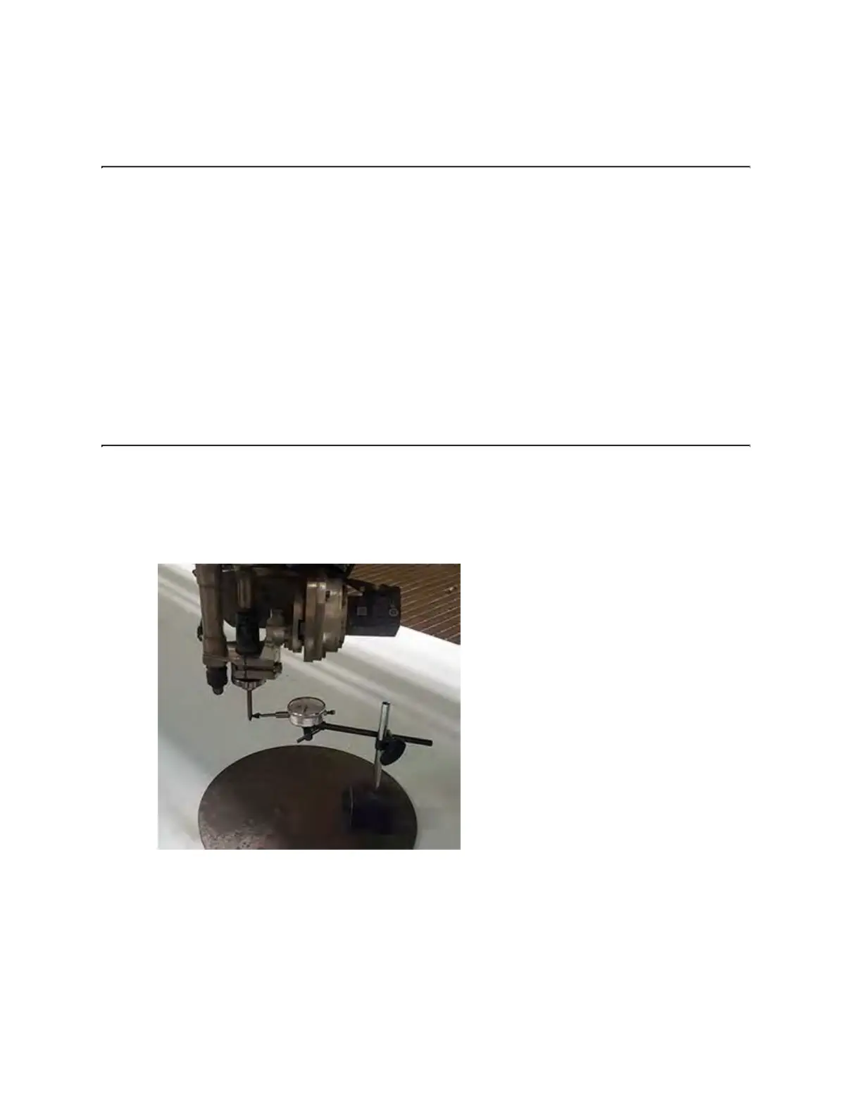
1. Attach the chisel tip to the plunger of the dial indicator, and then install the indicator onto the
magnetic base.
2. Place the ferrous plate into position just under the motors, and then place the base onto the
plate and engage the magnet.
© 2021 Flow International Corp.
Retrieved from Flow KB on April 19, 2021 PST
Calibrations and alignments